Hikvision DS-KIS901-P Käyttöohje
Hikvision Intercomssteem DS-KIS901-P
Lue alta 📖 käyttöohje suomeksi merkille Hikvision DS-KIS901-P (16 sivua) kategoriassa Intercomssteem. Tämä opas oli hyödyllinen 71 henkilölle ja sai 4.6 tähden keskimäärin 9 käyttäjältä
Sivu 1/16
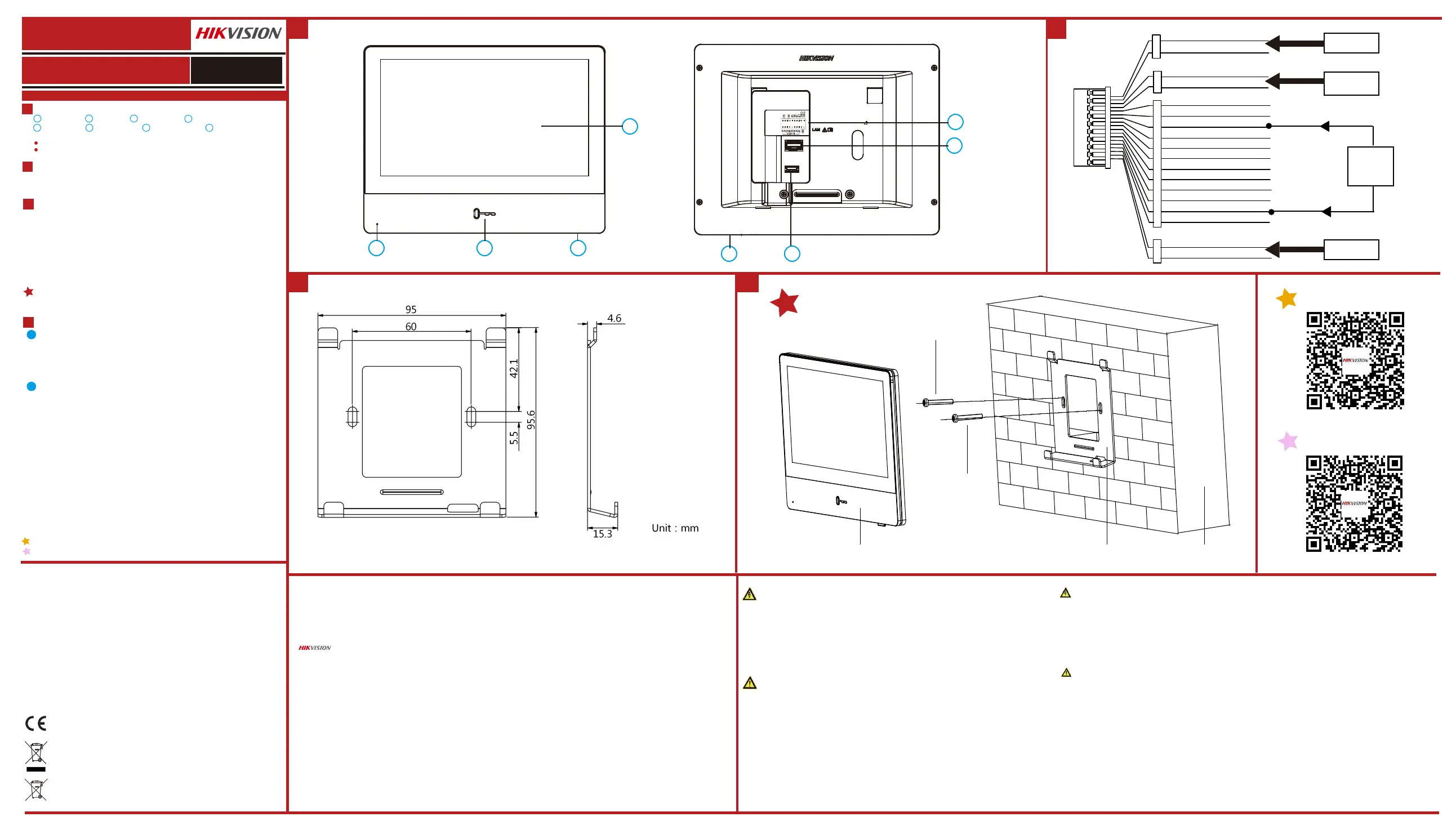
Diagram References
Regulatory Informaon
FCC Informaon
Please take aenon that changes or modificaon not expressly approved by the party responsible for
compliance could void the user’s authority to operate the equipment.
FCC compliance: This equipment has been tested and found to comply with the limits for a Class B digital
device, pursuant to part 15 of the FCC Rules. These limits are designed to provide reasonable protecon
against harmful interference in a residenal installaon. This equipment generates, uses and can radiate radio
frequency energy and, if not installed and used in accordance with the instrucons, may cause harmful
interference to radio communicaons. However, there is no guarantee that interference will not occur in a
parcular installaon. If this equipment does cause harmful interference to radio or television recepon,
which can be determined by turning the equipment off and on, the user is encouraged to try to correct the
interference by one or more of the following measures:
—Reorient or relocate the receiving antenna.
—Increase the separaon between the equipment and receiver.
—Connect the equipment into an outlet on a circuit different from that to which the receiver is connected.
—Consult the dealer or an experienced radio/TV technician for help.
FCC Condions
This device complies with part 15 of the FCC Rules. Operaon is subject to the following two condions:
1. This device may not cause harmful interference.
2. This device must accept any interference received, including interference that may cause undesired
operaon.
● All the electronic operaon should be strictly compliance with the electrical safety regulaons, fire
prevenon regulaons and other related regulaons in your local region.
● Please use the power adapter, which is provided by normal company. The power consumpon cannot
be less than the required value.
● Do not connect several devices to one power adapter as adapter overload may cause over-heat or fire
hazard.
● Please make sure that the power has been disconnected before you wire, install or dismantle the device.
● When the product is installed on wall or ceiling, the device shall be firmly fixed.
● If smoke, odors or noise rise from the device, turn off the power at once and unplug the power cable,
and then please contact the service center.
● If the product does not work properly, please contact your dealer or the nearest service center. Never
aempt to disassemble the device yourself. (We shall not assume any responsibility for problems caused
by unauthorized repair or maintenance.)
● Do not drop the device or subject it to physical shock, and do not expose it to high electromagnesm
radiaon. Avoid the equipment installaon on vibraons surface or places subject to shock (ignorance can
cause equipment damage).
● Do not place the device in extremely hot (refer to the specificaon of the device for the detailed
operang temperature), cold, dusty or damp locaons, and do not expose it to high electromagnec
radiaon.
● The device cover for indoor use shall be kept from rain and moisture.
● Exposing the equipment to direct sun light, low venlaon or heat source such as heater or radiator is
forbidden (ignorance can cause fire danger).
● Do not aim the device at the sun or extra bright places. A blooming or smear may occur otherwise (which
is not a malfuncon however), and affecng the endurance of sensor at the same me.
● Please use the provided glove when open up the device cover, avoid direct contact with the device cover,
because the acidic sweat of the fingers may erode the surface coang of the device cover.
● Please use a so and dry cloth when clean inside and outside surfaces of the device cover, do not use
alkaline detergents.
● Please keep all wrappers aer unpack them for future use. In case of any failure occurred, you need to
return the device to the factory with the original wrapper. Transportaon without the original wrapper may
result in damage on the device and lead to addional costs.
● Improper use or replacement of the baery may result in hazard of explosion. Replace with the same or
equivalent type only. Dispose of used baeries according to the instrucons provided by the baery
manufacturer.
Product Informaon
This product and - if applicable - the supplied accessories too are marked with "CE" and comply
therefore with the applicable harmonized European standards listed under the RE Direcve
2014/53/EU, the EMC Direcve 2014/30/EU, the LVD Direcve 2014/35/EU, the RoHS Direcve
2011/65/EU
2012/19/EU (WEEE direcve): Products marked with this symbol cannot be disposed of as
unsorted municipal waste in the European Union. For proper recycling, return this product to your
local supplier upon the purchase of equivalent new equipment, or dispose of it at designated
collecon points. For more informaon see: www.recyclethis.info
2006/66/EC (baery direcve): This product contains a baery that cannot be disposed of as
unsorted municipal waste in the European Union. See the product documentaon for specific
baery informaon. The baery is marked with this symbol, which may include leering to
indicate cadmium (Cd), lead (Pb), or mercury (Hg). For proper recycling, return the baery to your
supplier or to a designated collecon point. For more informaon see:www.recyclethis.info
Safety Instrucon
Cauons
Warnings
● Tous les éléments électroniques doivent respecter à la lere la réglementaon locale sur la sécurité des installaons électriques, sur
la prévenon des incendies et des réglementaons connexes en vigueur.
● Ulisez un adaptateur fourni par une entreprise agréée. La consommaon électrique ne doit pas être inférieure à la valeur exigée.
● Ne branchez pas plusieurs appareils sur un même adaptateur ; toute surcharge de l'adaptateur pouvant entraîner sa surchauffe ou
provoquer un incendie.
● Veillez à bien déconnecter la source d’alimentaon avant de câbler, installer ou démonter l’appareil.
● Lors de l'installaon au mur ou au plafond, assurez-vous que l'appareil est bien fixé.
● Si l'appareil dégage de la fumée ou une odeur suspecte, ou s'il émet des bruits inhabituels, éteignez-le et débranchez le câble
d'alimentaon, puis contactez le SAV.
● Si le produit ne fonconne pas correctement, contactez votre revendeur ou le SAV le plus proche. Vous ne devez en aucun cas essayer
de démonter le produit vous-même. (Nous déclinons toute responsabilité en cas de problèmes découlant d'une intervenon ou d'une
réparaon effectuée sans autorisaon.)
● Évitez de faire tomber l’appareil, de le heurter et de l'exposer à des rayonnements électromagnéques de forte intensité. Évitez
d'installer l'équipement sur des surfaces vibrantes ou à des emplacements subissant des chocs fréquents (au risque de l'endommager).
● N'installez pas l’appareil à un emplacement trop chaud ou trop froid (reportez-vous à la spécificaon de l’appareil pour connaître la
température de fonconnement précise), poussiéreux ou humide. Ne l'exposez pas non plus à des rayonnements électromagnéques
élevés.
● Le capot de l’appareil pour installaon intérieure ne doit pas être exposé à la pluie, ni à l'humidité.
● Il est formellement interdit d'exposer l'équipement directement au soleil, à un environnement mal venlé ou à une source de chaleur
telle qu'une chaudière ou un radiateur (au risque de provoquer un incendie).
● N'orientez pas l’appareil vers le soleil ou des sources de lumière très vive. Dans le cas contraire, un voile ou des traînées risquent de se
former (ce qui ne constue toutefois pas un dysfonconnement) et la résistance du capteur peut également être affectée.
● Ulisez le gant fourni pour ouvrir le capot du dôme et évitez tout contact direct avec celui-ci, l'acidité de la sudaon des doigts
pouvant éroder le revêtement du capot de l’appareil.
● Ulisez un chiffon doux et sec pour neoyer les surfaces intérieures et extérieures du capot de l’appareil. N'ulisez pas de détergents
alcalins.
● Conservez tous les emballages ; ils pourront vous resservir ultérieurement. En cas de panne, renvoyez l’appareil à l'usine dans son
emballage d'origine. Si l’appareil est transporté hors de son emballage d'origine, il risque d'être abîmé, entraînant des frais
supplémentaires.
● Une mauvaise ulisaon de la baerie ou un remplacement erroné peut entraîner un risque d'explosion. Ne la remplacez que par une
baerie idenque ou de type équivalent. Meez les baeries usagées au rebut conformément aux instrucons du fabricant.
Consignes de sécurité
Précauons
Averssements :
Appearance
Installaon
Before you begin:
Wall Mounng
Acvate Indoor Staon
1
3
Geng Started
4
Wiring
2
Display Screen
Microphone
Unlock Buon
123
4
567
1. Tools that you need to prepare for installaon: Make sure the device in the package
is in good condion and all the assembly parts are included.
2. The power supply the indoor staon supports is 12 VDC. Please make sure your
power supply matches your indoor staon.
3. Make sure all the related equipment is power-off during the installaon.
4. Check the product specificaon for the installaon environment.
1. Fix the wall mounng plate to the wall with 2 supplied screws.
2. IPut the indoor staon on the holder of the wall mounng plate.
1. Choose Language and tap Next.
2. Set network parameters and tap Next.
- Edit Local IP, Subnet Mask and Gateway parameters.
- Enable DHCP, the device will get network parameters automacally.
3. Configure the indoor staon and tap Next.
a. Choose Indoor Staon Type.
b. Edit Floor and Room No.
4. Linked related devices and tap Next. If the device and the indoor staon are in the
same LAN, the device will be displayed in the list. Tap the device or enter the serial No.
to link.
a. Tap the door staon in the list to link.
b. Tap the sengs icon to pop up the Network Sengs page.
c. Edit the network parameters of the door staon manually or enable DHCP to get
the network parameters automacally.
d. Oponal: Enable Synchronize Language to synchronize the Language of door
staon with indoor staon.
e. Tap OK to save the sengs.
5. Tap Finish to save the sengs.
1. Power on the device. It will enter the acvaon page automacally.
2. Create a password and confirm it.
3. Tap OK to acvate the indoor staon.
Debugging PortNetwork Interface
SD Card Slot
Loudspeaker
8
Alarm Terminal
Note:
The debugging port is used for debugging only.
The Unlock key is valid only when does the indoor staon speak with the door staon or open the
live view of the door staon.
Refer to Video Intercom Indoor Staon Configuraon Guide (scan the QR code) for details.
Refer to Video Intercom Indoor Staon Operaon Guide (scan the QR code) for details.
You are required to acvate the device first by seng a strong password for it before
you can use the device.
1
Quick Configuraon
2
DS-KIS901-P
DS-KH8350-WTE1
Video Intercom Network Indoor Staon
Video Intercom Network Bundle
ENGLISH
UD18305B
There are 20 pins in the terminal on the rear panel of the indoor staon 2 RS-485
pins, 2 power pins, 2 GND pins, 2 alarm output pins, 8 alarm input pins, and 2
reserved pins.
It supports wall mounng. There are two installaon modes.
The wall mounng plate is are required to install the indoor staon onto the wall.
The dimension of wall mounng plate is shown.
©2020 Hangzhou Hikvision Digital Technology Co., Ltd.
It includes instrucons on how to use the Product. The soware embodied in the Product is governed by the user license agreement covering that Product.
About this Manual
This Manual is subject to domesc and internaonal copyright protecon. Hangzhou Hikvision Digital Technology Co., Ltd. (“Hikvision”) reserves all rights to
this manual. This manual cannot be reproduced, changed, translated, or distributed, parally or wholly, by any means, without the prior wrien permission
of Hikvision.
Trademarks
and other Hikvision marks are the property of Hikvision and are registered trademarks or the subject of applicaons for the same by Hikvision
and/or its affiliates. Other trademarks menoned in this manual are the properes of their respecve owners. No right of license is given to use such
trademarks without express permission.
Legal Disclaimer
TO THE MAXIMUM EXTENT PERMITTED BY APPLICABLE LAW, THE PRODUCT DESCRIBED, WITH ITS HARDWARE, SOFTWARE AND FIRMWARE, IS PROVIDED “AS
IS”, WITH ALL FAULTS AND ERRORS, AND HIKVISION MAKES NO WARRANTIES, EXPRESS OR IMPLIED, INCLUDING WITHOUT LIMITATION, MERCHANTABILITY,
SATISFACTORY QUALITY, FITNESS FOR A PARTICULAR PURPOSE, AND NON-INFRINGEMENT OF THIRD PARTY. IN NO EVENT WILL HIKVISION, ITS DIRECTORS,
OFFICERS, EMPLOYEES, OR AGENTS BE LIABLE TO YOU FOR ANY SPECIAL, CONSEQUENTIAL, INCIDENTAL, OR INDIRECT DAMAGES, INCLUDING, AMONG
OTHERS, DAMAGES FOR LOSS OF BUSINESS PROFITS, BUSINESS INTERRUPTION, OR LOSS OF DATA OR DOCUMENTATION, IN CONNECTION WITH THE USE OF
THIS PRODUCT, EVEN IF HIKVISION HAS BEEN ADVISED OF THE POSSIBILITY OF SUCH DAMAGES.
REGARDING TO THE PRODUCT WITH INTERNET ACCESS, THE USE OF PRODUCT SHALL BE WHOLLY AT YOUR OWN RISKS. HIKVISION SHALL NOT TAKE ANY
RESPONSIBILITIES FOR ABNORMAL OPERATION, PRIVACY LEAKAGE OR OTHER DAMAGES RESULTING FROM CYBER ATTACK, HACKER ATTACK, VIRUS
INSPECTION, OR OTHER INTERNET SECURITY RISKS; HOWEVER, HIKVISION WILL PROVIDE TIMELY TECHNICAL SUPPORT IF REQUIRED.
SURVEILLANCE LAWS VARY BY JURISDICTION. PLEASE CHECK ALL RELEVANT LAWS IN YOUR JURISDICTION BEFORE USING THIS PRODUCT IN ORDER TO
ENSURE THAT YOUR USE CONFORMS THE APPLICABLE LAW. HIKVISION SHALL NOT BE LIABLE IN THE EVENT THAT THIS PRODUCT IS USED WITH ILLEGITIMATE
PURPOSES.
IN THE EVENT OF ANY CONFLICTS BETWEEN THIS MANUAL AND THE APPLICABLE LAW, THE LATER PREVAILS.
Data Protecon
During the use of device, personal data will be collected, stored and processed. To protect data, the development of Hikvision devices incorporates privacy
by design principles. For example, for device with facial recognion features, biometrics data is stored in your device with encrypon method; for fingerprint
device, only fingerprint template will be saved, which is impossible to reconstruct a fingerprint image.
As data controller, you are advised to collect, store, process and transfer data in accordance with the applicable data protecon laws and regulaons,
including without limitaon, conducng security controls to safeguard personal data, such as, implemenng reasonable administrave and physical security
controls, conduct periodic reviews and assessments of the effecveness of your security controls.
12
33
1
234
7
8
56
RS-485+
RS-485-
Blue
Green
Red
DC 12V IN
GND
ALARM_OUT2
ALARM_IN1
ALARM_IN2
ALARM_IN3
ALARM_IN4
ALARM_IN5
ALARM_IN6
ALARM_IN7
ALARM_IN8
Black
Black
Black
Red
Red
ALARM_OUT1
Yellow
Yellow
White
White
White
White
White
White
White
White
GND
GND
Res
Res
Security
Control
Device
Reserved
Reserved
Power
Input
Screw
Screw
Indoor Station
Mounting Plate
Wall
Tuotetiedot
| Merkki: | Hikvision |
| Kategoria: | Intercomssteem |
| Malli: | DS-KIS901-P |
Tarvitsetko apua?
Jos tarvitset apua merkille Hikvision DS-KIS901-P esitä kysymys alla ja muut käyttäjät vastaavat sinulle
Intercomssteem Hikvision Käyttöohjeet

27 Maaliskuuta 2025
27 Maaliskuuta 2025
5 Tammikuuta 2025
16 Lokakuuta 2024
16 Lokakuuta 2024
16 Lokakuuta 2024
16 Lokakuuta 2024
16 Lokakuuta 2024
16 Lokakuuta 2024
16 Lokakuuta 2024
Intercomssteem Käyttöohjeet
Viimeisimmät Intercomssteem Käyttöohjeet
28 Maaliskuuta 2025
27 Maaliskuuta 2025
27 Maaliskuuta 2025
20 Helmikuuta 2025
6 Helmikuuta 2025
30 Tammikuuta 2025
25 Tammikuuta 2025
25 Tammikuuta 2025
24 Tammikuuta 2025
24 Tammikuuta 2025