Oreg RTR-E 8011 Käyttöohje
Oreg Ei luokiteltu RTR-E 8011
Lue alta 📖 käyttöohje suomeksi merkille Oreg RTR-E 8011 (2 sivua) kategoriassa Ei luokiteltu. Tämä opas oli hyödyllinen 56 henkilölle ja sai 4.8 tähden keskimäärin 3 käyttäjältä
Sivu 1/2
468 931 014 319
t
Mounting and
Operating Instructions
for room thermostats
RTR-E 8…
General Notes
The device may only be opened and installed accor-
ding to the circuit diagram on the device or these
instructions by a qualified electrician. The existing
safety regulations must be observed. Appropriate
installation measures must be taken to achieve the re-
quirements of protection class II. This independently
mountable electromechanical device is designed
for controlling the temperature in dry and enclosed
rooms only under normal conditions. The device
confirms to EN 60730, it works according operating
principle 1C.
When commissioning the room temperature regula-
tor, please note that the bi metallic element requires a
certain time to adjust itself to the room temperature.
Immediately after installation the switch-point will
deviate from the room temperature. Switch-point ac-
curacy is established only after about 1-2 hours ope-
ration.
Field of application
The room temperature controller is intended for the
control of temperature within enclosed dry areas with
typical surrounding.
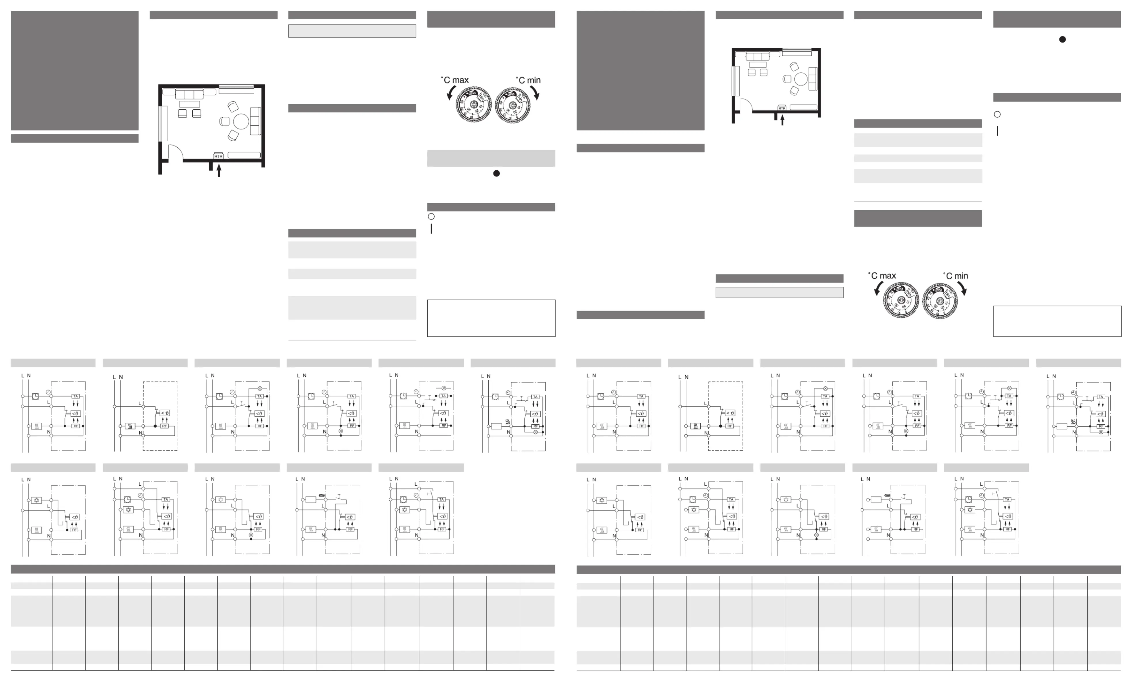
Mounting
Location:
• The preferred mounting location is on an inner wall
opposite the heating source
radiator
radiator
Room
Temperature Controlle
r
• Mounting height: approximately 1,5 m above floor
level.
• Avoid outer walls and drafts from win dows and doors.
• Ensure that the normal convection currents of the
room can reach the controller unimpeded. The
controller should not be mounted on the wall within
shelv ing or behind curtains or similar coverings.
• External heat has an adverse effect on control accu-
racy. Avoid direct sunshine and the immediate vici-
nity of televisions, radios, heating appliances, lamps,
chimneys and heating pipes.
• If fitted in a multi-way carrier, the controller should
always be put in the lowest position.
• Combination with dimmers! If the controller and a
dimmer are being fitted in a common carrier, then a
switch or a socketoutlet must be interposed between
the controller and the dimmer, since the latter is
source of heat.
Electrical connection
Caution! De-energize the electric circuit first
Perform the steps described below:
• Pull off the temperature dial
• Release the fixing screw
• Remove the upper part of the casing
• Connect acc. to circuit diagram (see bottom of casing)
Wiring diagram symbols
L = Line
N = Neutral
N= Connection for time-switch signal
for temperature reduction
U= Load connection Heating
P= Load connection Cooling
RF = Resistance for thermal feedback
TA = Resistance for night-time reduction
of room temperature.
Lamp red: Mains on
Lamp red: Call for heat
Lamp green: Temperature set back on
Technical Data
Relative humiditymax. 95 % without
condensation
Rated impulse voltage4 KV
Pollution degree2
Ball pressure test temperature75 ±2 °C
Voltage and Current for the purposes
of interfernce measurements
230 V; 0.1 A
Energy class
(acc. EU 811/2013, 812/2013, 813/2013,
814/2013)
I = 1 %
Limiting the temperature
setting range
The room temperature controller is factory-set to its
full adjustment range of 5 to 30°C (Fig. 1).
There are two adjustment rings on the ad justing knob.
These enable the temperature adjustment range to be
limited as desired
Fig. 1
Limiting the temperature setting range
Scale for temperature setting with
codemarks
P= ~ 5 °C = ~ 20 °C
2
= ~ 10 °C
5
= ~ 25 °C
3
= ~15 °C
6
=~ 30 °C
Symbols
OFF
ON
É
Continuous day-time setting
ë
Continuous night-time setting
N
Automatic (night-time reduction remotely
controllable via time-switch)
ÜAuxiliary heating
468 931 014 319
D
Montage- und
Bedienungsanleitung
für
Raumtemperaturregler
RTR-E 8…
Zur Beachtung!
Das Gerät darf nur durch einen Elektrofachmann
geöffnet und gemäß dem Schaltbild am Gerät bzw.
dieser Anleitung installiert werden. Dabei sind die
bestehenden Sicherheitsvorschriften zu beachten. Um
die Anforderungen der Schutzklasse II zu erreichen,
müssen entsprechende Installationsmaßnahmen
ergriffen werden. Dieses unabhängig montierbare
elektro mechanische Gerät dient der Regelung
der Temperatur ausschließlich in trockenen und
geschlossenen Räumen, mit üblicher Umgebung.
Dieses Gerät entspricht der EN 60730, es arbeitet nach
der Wirkungsweise 1C.
Bei Inbetriebnahme des Raumtemperaturreglers ist
zu beachten, dass das Thermobimetall eine ge wisse
Zeit benötigt, um sich der Raumtemperatur anzu-
passen. Unmittelbar nach der Montage oder nach
Abschaltung der Nachtabsenkung wird deshalb der
Schaltpunkt von der Raumtemperatur abweichen. Die
Schaltpunkt genauigkeit ist erst nach ca. 1 bis 2 Stun-
den Betriebs dauer gegeben.
Zur schnelleren Anfangsaufheizung und Abkürzung
der Anfangsausgleichung wird daher emp fohlen die
Einstelltemperatur höher als ge wünscht einzustellen.
Nach Erreichen der Tem peratur kann dann die Tempe-
ratureinstellung wieder auf den gewünschten Sollwert
gebracht werden.
Verwendungsbereich
Montageort:
• Der Raumtemperaturregler dient zur Regelung der
Temperatur in geschlossenen Räumen, wie Woh-
nungen, Schulen, Sälen, Werkstätten usw. mit üb-
licher Umgebung.
Montageort
• Eine Installation gegenüber der Heizquelle an einer
Innenwand ist zu bevorzugen.
Heizkörper
Raumtemperatur-
regler
Heizkörper
• Montagehöhe: ca. 1,5 m über dem Fußboden.
• Vermeiden Sie Außen wände und Zugluft von Fens-
tern und Türen.
• Achten Sie darauf, dass die normale Konvektions-
luft des Raumes den Regler ungehindert erreicht.
Der Regler soll daher nicht innerhalb von Regal-
wänden oder hinter Vor hängen und ähnlichen Ab-
deckungen montiert werden.
• Fremdwärme beeinflußt die Regelgenauigkeit
nachteilig.
Vermeiden Sie daher:
direkte Sonneneinstrahlung, die Nähe von Fern seh-,
Rundfunk- und Heizgeräten, Lampen, Kaminen und
Heizungsrohren.
• Auch ein Dimmer erzeugt Wärme!
Wird der Regler zusammen mit einem Dimmer in
einem gemeinsamen Schalterrahmen montiert, soll
der Abstand zwischen beiden möglichst groß sein.
Bei einer Anordnung übereinander muß der Regler
unterhalb des Dimmers sitzen.
Elektrischer Anschluss
Achtung! Stromkreis spannungsfrei schalten
Anschluss in folgenden Schritten:
• Abziehen des Temperatur-Einstellknopfes
• Lösen der Befestigungsschraube
• Abnehmen des Gehäuseoberteils
• Anschluss gemäß Schaltbild (s. Gehäuseboden).
Kurzbeschreibung im Schaltbild
L = Außenleiter (Phase)
N = Neutralleiter (früher Mp)
>= Anschluß für Uhrsignal zur Temperatur-
absenkung
U= Lastanschluß Heizen
P= Lastanschluß Kühlen
RF = Widerstand für thermische Rückführung
TA = Widerstand für Nachtabsenkung der Raum-
temperatur
Anzeigelampe rot: Netz ein
Anzeigelampe rot: Regler fordert Wärme an
Anzeigelampe grün Temperaturab sen kung ein
Technische Daten
Max rel. Raumfeuchtemax 95 %,
nicht kondensierend
Bemessungsstoßspannung 4 KV
Verschmutzungsgrad2
Temperatur für die
Kugeldruckprüfung
75 ± 2 °C
Spannung und Strom
für Zwecke der EMV-
Störaussendungsprüfungen
230 V; 0,1 A
Energie-Klasse
(nach EU 811/2013, 812/2013, 813/2013,
814/2013)
I = 1 %
Einengen des
Temperatureinstellbereiches:
Werkseitig ist der Raumtemperaturregler auf den
maxi malen Einstellbereich von 5 - 30°C eingestellt
(siehe Bild 1).
Im Einstellknopf befinden sich 2 Einstell ringe.
Mit diesen kann der Temperatureinstellbereich belie-
big eingestellt werden.
Bild 1: Einengen des Temperatureinstell bereiches
Skalen zur Temperatureinstellung
mit Merkziffern
P= ca. 5 °C = ca. 20 °C
2
= ca. 10 °C
5
= ca. 25 °C
3
= ca. 15 °C
6
= ca. 30 °C
Symbole
AUS
EIN
É
dauernd gewählte Temperatur
ë
dauernd gewählte Absenktemperatur
N
über Zeitschaltuhr gesteuerte Umschaltung
zwischen Tag- und Nachttemperatur
ÜZusatzheizung
Technische Daten
TypRTR-E 8001RTR-E 8002RTR-E 8003RTR-E 8011RTR-E 8012RTR-E 8015RTR-E 8021RTR-E 8022RTR-E 8025RTR-E 8031RTR-E 8032RTR-E 8033RTR-E 8051RTR-E 8063RTR-E 8065
Temperaturbereich:5…30°C5…30°C5…30°C5…30°C5…30°C5…30°C5…30°C5…30°C5…30°C5…30°C5…30°C5…30°C5…30°C5…30°C5…30°C
Nennspannung:250V~24V~250V~250V~24V~250V~250V~24V~250V~250V~24V~250V~250V~250V~250V~
Nennstrom
(cosϕ= 0,6)
U Heizen
P Kühlen
10mA…10(4)A
––
10mA…10(4)A
––
10mA…10(4)A
10mA…10(4)A
––
10mA…10(4)A
––
10mA…10(4)A
––
10mA…10(4)A
––
10mA…10(4)A
––
10mA…10(4)A
––
10mA…10(4)A
10mA…5(2)A
10mA…10(4)A
10mA…5(2)A
10mA…10(4)A
10mA…5(2)A
10mA…10(4)A
10mA…(2)A
10mA…10(4)A
––
10mA…10(4)A
10mA…5(2)A
Schaltleistung
U Heizen
P Kühlen
2,3 KW
––
240W *
––
2,3 KW
––
2,3 KW
––
240W *
––
2,3 KW
––
2,3 KW
––
240W *
––
2,3 KW
––
2,3 KW
1,1KW
240W **
120W **
2,3 KW
1,1KW
2,3 KW
1,1KW
2,3 KW
––
2,3 KW
1,1KW
Schalttemperatur-
differenz:
ca. 0,5Kca. 0,5Kca. 0,5Kca. 0,5Kca. 0,5Kca. 0,5Kca. 0,5Kca. 0,5Kca. 0,5Kca. 0,5Kca. 0,5Kca. 0,5Kca. 0,5Kca. 0,5Kca. 0,5K
Temperaturabsenk.ca. 4Kca. 4Kca. 4Kca. 4Kca. 4Kca. 4Kca. 4Kca. 4Kca. 4Kca. 4K––––––––––
* Bei DC max. 100W** Bei DC max. 30W
*
Dieses Produkt darf nicht über den Hausmüll
entsorgt werden. Bitte nur in speziellen Ein-
richtungen für Elektronikschrott entsorgen. Er-
kundigen Sie sich bei den örtlichen Behörden
zur Recycling Beratung.
*
This product should not be disposed of with
household waste. Please recycle the products
where facilities for electronic waste exist. Check
with your local authorities for recycling advice.
RTR-E 8001 / RTR-E 8002RTR-E 8011 / RTR-E 8012RTR-E 8015RTR-E 8021 / RTR-E 8022RTR-E 8025
RTR-E 8033RTR-E 8051RTR-E 8063RTR-E 8065RTR-E 8031 / RTR-E 8032
RTR-E 8003
Technical data
Typ
RTR-E 8001RTR-E 8002RTR-E 8003RTR-E 8011RTR-E 8012RTR-E 8015RTR-E 8021RTR-E 8022RTR-E 8025RTR-E 8031RTR-E 8032RTR-E 8033RTR-E 8051RTR-E 8063RTR-E 8065
Temperature range:
5…30°C5…30°C5…30°C5…30°C5…30°C5…30°C5…30°C5…30°C5…30°C5…30°C5…30°C5…30°C5…30°C5…30°C5…30°C
Operating voltage:
250V~24V~250V~250V~24V~250V~250V~24V~250V~250V~24V~250V~250V~250V~250V~
Switching current
(cos = 0,6)ϕ
U Heating
P Cooling
10mA…10(4)A
––
10mA…10(4)A
––
10mA…10(4)A
10mA…10(4)A
––
10mA…10(4)A
––
10mA…10(4)A
––
10mA…10(4)A
––
10mA…10(4)A
––
10mA…10(4)A
––
10mA…10(4)A
10mA…5(2)A
10mA…10(4)A
10mA…5(2)A
10mA…10(4)A
10mA…5(2)A
10mA…10(4)A
10mA…(2)A
10mA…10(4)A
––
10mA…10(4)A
10mA…5(2)A
Switching capacity
U Heating
P Cooling
2,3 KW
––
240W *
––
2,3 KW
––
2,3 KW
––
240W *
––
2,3 KW
––
2,3 KW
––
240W *
––
2,3 KW
––
2,3 KW
1,1KW
240W **
120W **
2,3 KW
1,1KW
2,3 KW
1,1KW
2,3 KW
––
2,3 KW
1,1KW
Switching tempera-
ture differential
ca. 0,5Kca. 0,5Kca. 0,5Kca. 0,5Kca. 0,5Kca. 0,5Kca. 0,5Kca. 0,5Kca. 0,5Kca. 0,5Kca. 0,5Kca. 0,5Kca. 0,5Kca. 0,5Kca. 0,5K
Temperature set-back
ca. 4Kca. 4Kca. 4Kca. 4Kca. 4Kca. 4Kca. 4Kca. 4Kca. 4Kca. 4K––––––––––
* with DC max. 100W** with DC max. 30W
RTR-E 8001 / RTR-E 8002RTR-E 8011 / RTR-E 8012RTR-E 8015RTR-E 8021 / RTR-E 8022RTR-E 8025
RTR-E 8033RTR-E 8051RTR-E 8063RTR-E 8065RTR-E 8031 / RTR-E 8032
RTR-E 8003
Tuotetiedot
| Merkki: | Oreg |
| Kategoria: | Ei luokiteltu |
| Malli: | RTR-E 8011 |
Tarvitsetko apua?
Jos tarvitset apua merkille Oreg RTR-E 8011 esitä kysymys alla ja muut käyttäjät vastaavat sinulle
Ei luokiteltu Oreg Käyttöohjeet

15 Lokakuuta 2024
15 Lokakuuta 2024
15 Lokakuuta 2024
15 Lokakuuta 2024
15 Lokakuuta 2024
Ei luokiteltu Käyttöohjeet
Viimeisimmät Ei luokiteltu Käyttöohjeet
9 Huhtikuuta 2025
9 Huhtikuuta 2025
9 Huhtikuuta 2025
9 Huhtikuuta 2025
9 Huhtikuuta 2025
9 Huhtikuuta 2025
9 Huhtikuuta 2025
9 Huhtikuuta 2025
9 Huhtikuuta 2025
9 Huhtikuuta 2025