Netter Vibration NEG 50120 Käyttöohje

Lue alta 📖 käyttöohje suomeksi merkille Netter Vibration NEG 50120 (45 sivua) kategoriassa Ei luokiteltu. Tämä opas oli hyödyllinen 13 henkilölle ja sai 4.3 tähden keskimäärin 7 käyttäjältä

Sivu 1/45
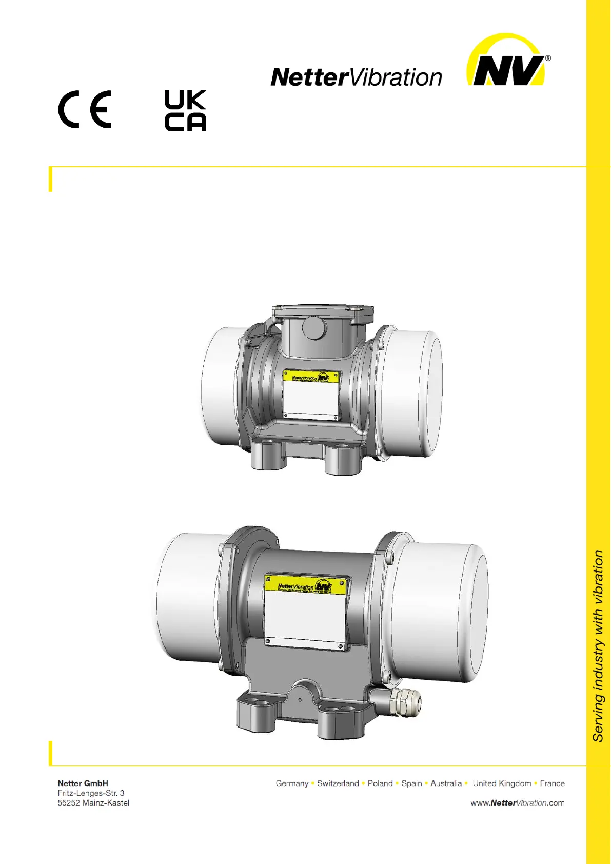
Operating instructions for
electric external vibrators
Series NEA/NEG/NEG S/NES/CIN
Sept. 2023
No. 1929E
Page 1/45
These operating instructions apply to:
2
Contents
1 General information 3
2 Safety 6
3 Technical data 12
4 Design and function 15
5 Transport and storage 16
6 Installation 17
7 Start-up and operation 21
8 Maintenance and servicing 28
9 Troubleshooting 33
10 35 Spare parts and accessories
11 37 Disposal
12 38 Annex
Please refer to the delivery note for the scope of delivery.
Check the packaging for possible transport damage. In the event of
damage to the packaging, check the contents for completeness and
possible damage. Inform the carrier in the case of damage.
The electric external vibrators of the series NEA, NEG, NEG S, NES
and CIN are hereafter referred to as "NEA/NEG".
Document no.
1929E
Version no.
4
Date of issue
Sept. 2023
Scope of
delivery
Designation
Version of
document
General information
3
1 General information
Before installing the NEA/NEG read these instructions carefully. It is the
basis for any action when dealing with the NEA/NEG, and may be used for
training purposes. The instructions should be subsequently stored at the
operation site.
The target group for these instructions is technical sta, who have basic
knowledge of mechanics, electrics and explosion protection.
Only complying technical sta may work on the NEA/NEG.
The NEA/NEG may only be installed, put into operation, maintained, trou-
bleshot and disassembled by persons authorised by the operator.
This documentation is protected by copyright.
Netter
Vibration reserves all rights such as translations, reprinting and re-
production of the instructions, as well as parts thereof.
All technical information, data and instructions for installation, operation
and maintenance in these instructions are based on the latest information
available at the time of printing and take our past experience to the best of
our knowledge into account.
No claims can be derived from the information, illustrations and descrip-
tions in these operating instructions.
The manufacturer does not assume liability for damages resulting from:
failure to observe the instructions,
improper use,
unauthorised repairs,
technical modications,
use of non-permissible spare parts.
Translations are made to the best of our knowledge.
Netter
Vibration does not assume liability for translation errors, even if the
translation was made by us or on our behalf. Only the original German text
remains binding.
The electric external vibrators of the series NEA, NEG, NEG S, NES and
CIN comply with the following directives:
EC Machinery Directive 2006/42/EC,
Supply of Machinery (Safety) Regulations 2008 (UK),
Electromagnetic Compatibility Directive 2014/30/EU,
Electromagnetic Compatibility Regulations 2016 (UK),
Low Voltage Directive 2014/35/EU,
Electrical Equipment (Safety) Regulations 2016 (UK).
Use and
storage
Target group
Copyright
Limitation of
liability
Directives
observed
General information
4
All electric external vibrators of the series NEA/NEG, labelled with the
Ex-Symbol on the type plate, comply with the following directives:
ATEX directive 2014/34 EU for equipment group II,
Equipment and Protective Systems Intended for use in Potentially Ex-
plosive Atmospheres Regulations 2016 for equipment group II (UK).
NEA/NEG of housing size 50 and 60 are suitable for use in potentially ex-
plosive areas of the category 3D in the zone 22.
NEA/NEG from housing size 100 upwards are suitable for use in potential-
ly explosive areas of the category 2D in the zone 21 and 22.
The main standards observed are indicated in the declaration of conformi-
ty.
Before using the NEA/NEG the operator must exclude the possibility that
the introduction of vibrational energy poses the risk of explosion.
The following instruction and warning symbols are used in these instruc-
tions:
DANGER
indicates an immediate danger.
Disregard of this notice will result in death or severe person-
al injuries.
WARNING
indicates a potential danger.
Disregard of this notice can result in death or severe per-
sonal injuries.
CAUTION
indicates a potentially dangerous situation.
Disregard of this notice can result in minor or moderate per-
sonal injuries.
NOTICE
indicates potential material damage.
Disregard of this notice can result in material damage.
IMPORTANT
indicates actions, methods or notes that are not relative to safety, e.g. use-
ful information and tips.
Instruction
and warning
symbols
Personal
injuries
Material
damages
Notes
General information
5
Environmentally safe disposal
indicates the obligation of environmentally safe disposal.
Explosion prevention
indicates information on explosion prevention.
When operating the NEA/NEG in potentially explosive areas all notes,
marked with the Ex-symbol , must be observed.
Explanations of abbreviations in the type designation:
XXX YYZZZZ-WWW
XXX indicates the type of vibrator (three-phase or single-phase):
= single-phase alternating current NEA
= 3-phase alternating current NEG
= 3-phase alternating current (stainless steel housing) NES
= 3-phase alternating current CIN
YY indicates the polarity:
= 2 poles 50
= 4 poles 25
= 6 poles 16
= 8 poles 12
ZZZZ indicates the centrifugal force in daN (Decanewton).
WWW indicates special features:
= 130 °C PTC thermistor installed (standard from housing size 170 K
upwards)
= 120 °C PTC thermistor installed K2
= 130 °C thermal protector with a normally closed (NC) switching TS
contact
= 120 °C thermal protector with a normally closed (NC) switching TS2
contact
= 200 - 240 V anti-condensation heater 0 - 50 W H
= 100 - 120 V anti-condensation heater 0 - 50 W H110
= Fully encapsulated stator (heavy duty) HD
Sux behind the type designation = stainless steel housing S
ATEX-notes
Type designa-
tions
Safety
6
2 Safety
The NEA/NEG are intended for generating circular vibrations. General ap-
plications are: loosening, conveying, sorting, compacting, separating bulk
materials and reducing friction. NEA/NEG are used for emptying bunkers,
as drives for conveyor troughs, sieves and vibrating tables.
The NEA/NEG are designed for installation in machines and may only be
put into operation, if it has been assured that the complete machine com-
plies with the regulations of the machinery directive.
Any other use is considered improper.
Installation, commissioning, maintenance and troubleshooting of the
NEA/NEG may only be performed by authorised qualied personnel, who
have basic knowledge of mechanics, electrics and explosion protection.
All handling of the NEA/NEG is the responsibility of the operator.
All accessory parts connected to the NEA/NEG, which ensure correct
operation and safety, must have the appropriate degree of protection for
this specic purpose.
IMPORTANT
Netter
Vibration assumes no liability for personal injuries and material
damages if technical changes to the product were made or the notices and
regulations in these instructions were not observed.
DANGER
Electric shock
An electric shock will result in serious injury or even death. The NEA/NEG
must be free of voltage during assembly, start-up, maintenance and trou-
bleshooting.
Observe the following ve safety rules:
1. Disconnect the NEA/NEG from the mains supply.
2. Secure the NEA/NEG against re-activation.
3. Establish that the NEA/NEG has no voltage.
4. Earth and short-circuit the power supply of the NEA/NEG.
5. Cover adjacent live parts or fence them o.
Intended use
Qualication
of qualied
personnel
Accessory
parts
Liability
Safety
rules
Safety
8
WARNING
Hazard of electrostatic discharge
When cleaning the NEA/NEG with a dry cloth there is a risk
of electrostatic discharge. A electrostatic discharge can lead
to an explosion due to ignition of an explosive atmosphere.
Only clean the NEA/NEG with a wet cloth.
Remove dust deposits regularly.
From housing size 100 onwards, the following warning
sticker is located on the NEA/NEG and must be ob-
served:
WARNING
Static electricity
The discharge of charged, isolated conductive parts can
cause ignitable sparks.
Connect the green-yellow protective conductor only to
the earth terminal in the terminal box.
Connect the earthing screw of the NEA/NEG to the po-
tential equalisation of the higher-level machine.
Include all components in the potential equalisation of
the machine.
Static
electricity
Static
electricity
Safety
9
WARNING
Hot surface
If the permissible operating conditions and the maintenance
requirements are not observed or if the vibrator does not t
the application, the housing surface may become very hot.
In Ex-zones there is a risk of ignition of an explosive atmos-
phere due to hot surfaces.
Observe all permissible operating conditions.
Carry out the specied maintenance work at the prede-
ned intervals.
Make sure that the vibrator is suitable for the application
and has been dimensioned correctly. Get advice from
application technicians of
Netter
Vibration.
For operating the NEA/NEG in potentially explosive at-
mosphere, it is mandatory to connect the PTC-
thermistor. This regulation does not apply if the vibrator
is not equipped with a PTC-thermistor.
NEA/NEG from housing size 170 upwards are equipped with thermistors
type PTC 130 °C as standard.
WARNING
Risk of injury and machine damage due to incorrect frequency and
unbalance settings
There is a risk of serious bodily injury due to uncontrolled machine move-
ments. Incorrect frequency and unbalance settings on the vibrators can
cause severe damage to the vibrators as well as the machine.
The vibrators may only be operated with the maximum permissible fre-
quency/unbalance combination.
When changing the frequency and unbalance settings of the vibrators,
observe the information on the type plate as well as the table for fre-
quency/unbalance setting on page . 22
Switch o the NEA/NEG immediately if you notice any irregularities in
its operation. Eliminate the fault before switching on again.
Hot surface
Frequency
and unbalance
settings
Safety
10
WARNING
Risk of injury while handling heavy parts
Risk of serious injury due to weight during transport and installation of the
NEA/NEG.
Observe the weight specications in the brochure of the vibrators.
Only qualied personnel may transport and install the NEA/NEG.
Use suitable load handling devices and slinging equipment.
Wear suitable personal protective equipment.
WARNING
Falling parts
The NEA/NEG or parts of the construction can come loose due to vibra-
tion. Falling parts can lead to severe personal injuries.
Use only suitable fastening screws and safety washer to attach the
NEA/NEG.
For attachment
Netter
Vibration recommends using fastening kits NBS.
Check the fastening screws after one hour of operation and thereafter
regularly (generally monthly).
Retighten the fastening screws, if necessary. Use a torque wrench and
tighten the screws crosswise.
In critical installation situations suitable securing is mandatory.
WARNING
Risk of injury due to rotating unbalances
During operation of the NEA/NEG without unbalance covers there is risk of
injury due to rotating unbalances.
Operate the NEA/NEG only with mounted unbalance covers.
CAUTION
Risk of burns due to hot surfaces
NEA/NEG can strongly heat up during operation. Direct contact may cause
burns.
Do not touch the NEA/NEG or the cable near the cable gland during
operation or shortly after being switched o.
Only operate the vibrators within the permissible ambient temperature,
according to chap. Technical data, starting on page . 12
Heavy parts
Falling parts
Rotating
Unbalances
Hot surfaces
Safety
11
For the operation of the NEA/NEG in ATEX zones, the following
conditions for safe use must be met:
When operating with a frequency converter in ATEX zones, the vibrator
must be equipped with a PTC thermistor. The PTC thermistor must be
connected and evaluated by the operator. The temperature of 130 °C
must not be exceeded.
A 130 °C PTC thermistor is installed from housing size 170 included
and up. The connection of this protection is mandatory for the user.
All safety devices shall operate independently of any measurement or
control devices required for operation, and comply with the EN 50495.
Resetting the safety devices shall only be manual.
Potential electrostatic charging hazard. Clean only with a wet cloth.
Opening the terminal box cover is not permitted if an explosive atmos-
phere is present.
Ambient temperature range: - °C/+55 °C. 20 °C … +40
The entries of the equipment shall be equipped with certied cable
glands or blanking elements with compatible modes of protection for
the intended use.
The cables and the relevant accessories (e.g. cable glands) must be suit-
able for an operating temperature at least:
+85 °C up to housing size 130 for an ambient temperature of +40 °C
(excepted the motors with 8 poles).
+90 °C up to housing size 130 for an ambient temperature of +40 °C
(only the motors with 8 poles).
+100 °C up to housing size 130 for an ambient temperature of +55 °C.
+105 °C for housing size 133 and up for an ambient temperature of
+40 °C.
+120 °C for housing size 133 and up for an ambient temperature of
+55 °C.
Special
conditions
Technical data
12
3 Technical data
Nominal volt-
age, nominal
frequency
The main voltage and the main frequency must comply with the nomi-
nal voltage and nominal frequency indicated on the type plate.
Permissible Voltage deviation: ±5%
Permissible frequency deviation: ±2%
Possible power supply with:
xed voltage and frequency or
frequency converter
Frequency changes and unbalance settings influence the centrifugal
force. During operation, the maximum permissible centrifugal force
(according to the type plate) must not be exceeded. The compliance
with the electromagnetic compatibility directive 2014/30/EU has to be
ensured.
In the ATEX-zones 21 and 22 the frequency converter may regu-
late the frequency between 20 Hz and 50 Hz or 20 Hz and 60 Hz at a
constant torque load (linear volt-hertz-curve). Please observe the max.
frequency on the type plate. For operation with frequency converter in
ATEX-zones the PTC thermistor must be connected.
Rotary speed
ranges
2-pole: 3000 min-1 Hz / 3600 min50 -1 Hz. 60
4-pole: 1500 min-1 Hz / 1800 min50 -1 Hz. 60
6-pole: 1000 min-1 Hz / 1200 min50 -1 Hz. 60
8-pole: 750 min-1 Hz / 900 min50 -1 Hz. 60
Permissible
ambient tem-
peratur*
- °C to 40 °C or 20
- °C to 55 20 °C
The maximum ambient temperature specied on the type plate must
not be exceeded.
These values are valid for operation with an ON-period of 100%. For
the following operation modes special requirements apply:
cycled operation or
frequency-controlled operation or
synchronous operation.
These must be clarified with
Netter
Vibration in individual cases.
Thermal over-
load protection
From housing size 170 upwards with thermistor type PTC °C as 130
standard.
For smaller vibrators available on request as initial equipment.
If the NEA/NEG is operated in environments with potentially explo-
sive dust (zone 21/22), it is mandatory to connect the PTC-thermistor.
This regulation does not apply if the unit is not equipped with a PTC-
thermistor.
Sound level
Depending on type ≤ dB(A) 70
The sound level is determined to a great extent by the surface upon
which the NEA/NEG is mounted (e.g. sheet metal). The sound level will
be amplied by non-silenced sheet metal.
* Higher temperatures are only possible after consultation with and written approval from
the application technicians of
Netter
Vibration.
Permissible
operating
conditions
Technical data
13
1
Type designation
2
Nominal voltage
3
Current
4
Phases / capacity
5
Power factor
6
Year of manufacture
7
Serial number
8
Max. ambient temperature
9
Insulation class / degree of
protection
10
Power output
11
Power input
12
Rotary speed / Nominal
frequency
13
Centrifugal force
14
Duty cycle
1
Type designation
2
Rotary speed
3
Nominal voltage
4
Current
5
Phases / capacity
6
Serial number
7
Year of manufacture
8
Insulation class / degree of
protection
NEG S: IP66; NES: IP69K
9
Power factor
10
Power output
11
Power input
12
Nominal frequency
13
Centrifugal force
14
Duty cycle
1
Type designation
2
Nominal voltage
3
Current
4
Phases
5
Year of manufacture
6
Serial number
7
Document number
8
Max. ambient temperature
9
Insulation class / degree of
protection
10
Power
11
Nominal frequency
12
Rotary speed
13
Centrifugal force
14
Duty cycle
15
ATEX certication
Type plate
CIN / NEA
from housing
size 100
Type plate
NEG S / NES
Type plate for
housing sizes
50 and 60
Technical data
14
1
Type designation
2
Nominal voltage
3
Current
4
Phases / capacity
5
Power factor
6
Year of manufacture
7
Serial number
8
Max. ambient temperature
9
Insulation class / degree of
protection
10
Power output
11
Power input
12
Rotary speed / nominal
frequency
13
Centrifugal force
14
Duty cycle
15
ATEX certication
The values can be found on the type plate. The type plate is located on
the housing.
For detailed technical data please refer to the brochure of the NEA/NEG.
Deviating customer-specic type plates (special designs) are possible.
Netter
Vibration recommends the following tightening torques [Nm]:
Type
M4
M5
M6
M8
M10
M12
M16
M20
M22
M24
M36
M42
Fastening
screws and
nuts, steel
Property class
8.8*
-
-
10
25
50
87
210
411
559
711
2500
4000
Fastening
screws for XS-
unbalances,
steel
Property class
12.9**
-
-
-
42
83
146
360
710
970
1225
4200
6700
Fastening
screws and
nuts, stainless
steel
-
-
8.8
21.4
44
74
183
-
-
-
-
-
Terminal plate
nuts, steel
1.2
2.0
3.0
6.5
13.5
-
-
-
-
-
-
-
* coecient of sliding friction 0.14 ** coecient of sliding friction 0.15
Screws as supplied, without additional lubrication.
Always use a torque wrench and tighten the screws crosswise.
Type
M13x1
M15x1
M20x1
M25x1.5
M30x2
M45x1.5
Locking nuts
(Pos. 21) see page 31
30
50
100
170
340
500
Type plate
from housing
size 100
Tightening
torques
Design and function
15
4 Design and function
Example: NEG 501140
Example: NEG 50120
Element
Function
1
Housing
Contains and protects the components of the
NEA/NEG.
2
Unbalance covers
Protect against grabbing into the unbalances.
3
Housing foot
Attach the NEA/NEG to the mounting surface.
4
Type plate
Shows model specific information and data.
5
Terminal box
Housing sizes 101 to 120:
terminal box integrated in housing
foot
Contains the electrical connections.
6
Cable gland
(depending on type)
Connect the NEA/NEG.
The electric external vibrators of the series NEA, NEG, NEG S, NES and
CIN are asynchronous motors with adjustable weights (unbalances)
mounted on their shaft ends.
The NEA/NEG generate circular vibrations, that means the vibrations act
in all directions of a plane.
The frequency can be controlled continuously with the help of frequency
converters.
The centrifugal force can be changed by adjustment of the unbalances.
Design
Function
Installation
17
6 Installation
Observe the safety instructions in chap. Safety, starting on page 6.
Weights and dimensions can be found in the NEA/NEG brochure.
Important: For NEA/NEG with housing size 101 to 120 the terminal box is
integrated in the housing foot. These vibrators must be electrically con-
nected before fastening.
The NEA/NEG can be operated in any position.
1. The feet of the NEA/NEG must lie completely on the surface Notice:
so that there is no tension in the housing when tightening the fas-
tening screw/screws, which could cause mechanical damage. The
mounting surface has to be at (±0.1 mm atness) and clean with no
paint residues or burn-ins.
2. The vibrators can be fastened with fastening screws of quality 8.8
(DIN 931 or 933). These must be secured with appropriate locking de-
vices and checked and retightened at regular intervals (usually month-
ly). For safe fastening
Netter
Vibration recommends the use of fas-
tening kits NBS consisting of a screw, a special lock washer and (for
NBS D) a nut.
Fasten the NEA/NEG with the fastening screws on the mounting sur-
face. Use a torque wrench and tighten the screws crosswise. Observe
the recommended values for screw sizes and tightening torques, see
chap. Technical data, from page . Higher tightening torques may 12
cause fracture of screws or tearing of threads.
Warning: Unsuitable screw connections may cause loosening of
the NEA/NEG by vibration and seriously injure persons and damage
material. A spark produced on impact can lead to the ignition of an
explosive atmosphere.
3. Use an additional safety device for critical
installation situations, e.g. steel cable NSE.
Use the wire cable clamps to set the safety
cable to the shortest possible cable length.
The safety cable must always be ten-
sioned.
Fastening
the NEA/NEG
Installation
18
The following requirements and conditions must be met to connect the
NEA/NEG electrically:
The permissible operating conditions must be met. Please refer to
chap. Technical data, page for operating conditions. 12
A suitable overload protection (1) must be
pre-connected to each vibrator. The motor
protection switches must be interlocked with
each other in pairs, so that in the event of a
motor failure, the power supply from both
motors is interrupted at the same time in or-
der not to cause uncontrolled vibrations
which can damage the system.
In zone 21/22 the motor protection switches
must be approved for applications in poten-
tially explosive areas.
If the vibrator is operated in areas with potentially explosive dust (zone
21/22), it is compulsory to connect the PTC-thermistor. This regulation
does not apply for NEA/NEG without a PTC-thermistor.
In areas with potentially explosive
dust (zone 21/22), an external
grounding must also be made via the
earth connection on the housing foot.
Only suitable, exible supply cables must be used for connecting the
NEA/NEG. The conductors in the supply cable for the connection of the
NEA/NEG to the mains must be temperature-resistant and have a suf-
ciently large cross-section, which is adapted to the cable length used.
The temperature resistance of the cables depends on the maximum
surface temperature (temperature class T, see section Special condi-
tions, page ) stated on the type plate. 11
When selecting the connection cables, consider that the cables are
mechanically stressed by vibration. Recommended cable types for
mains operation at 400 V, in potentially non-explosive atmosphere:
rubber hose line H07 RN-F or oil ex cable 110 CY.
For other voltages or other ambient conditions, the cables must be
adapted to the respective conditions and designed accordingly.
All electrical cables must be carefully laid and must be protected from
high temperatures, lubricants and sharp edges. Care must be taken to
ensure that the cables are not chafed through by vibrating parts. The
correct condition of the electrical cables with their plugs must be
checked at regular intervals (usually every six months). Detected errors
are to be eliminated immediately.
The cable fastening must be provided in close vicinity of the cable en-
trance.
Electrical
connection
Installation
19
The electrical parameters U, I, P on the type plate must be observed.
Tighten terminal plate nuts with pre-
scribed torque, see chap. Technical da-
ta, from page . Remember to put the 12
safety washer between the ring and the
nut and the vibration-damping insert
back.
The wire ends must be tted with suita-
ble insulated cable lugs, in order to pre-
vent the strands from splaying.
For operating the NEA/NEG in areas with potentially explosive dust
(housing size 50 and 60: zone 21; from housing size 100: zone 21 und
22) the mechanical protection of the housing must be guaranteed
(housing size 50 and 60: degree of protection IP65; from housing size
100: degree of protection IP66). After having disassembled the terminal
box cover or weight covers, the condition and correct positioning of the
seals has to be checked.
Open the terminal box to connect the NEG according to the type plate as
follows:
1
Earthing terminal for protective
conductor (green-yellow)
2
PTC-Thermistor connection
(optional, depending on the NEG
type)
Connect the NEG according to the type plate and the following circuit dia-
grams.
The green-yellow protective conductor must only be connected to the
earthing terminal.
Connection
examples NEG
Installation
20
Connection diagram
Series NEG / 3-phase current
Smaller voltage
Higher voltage
1: Earthing terminal for protective
conductor
2: PTC-Thermistor connection
(optional, depending on the NEG type)
1: Earthing terminal for protective
conductor
2: PTC-Thermistor connection
(optional, depending on the NEG type)
Connect the NEA according to the information on the type plate. Excluded
from this is the NEA 504 operated without a capacitor.
1
capacitor box
L1
outer conductor (brown)
N
neutral conductor (blue)
PE
protective conductor
(green-yellow)
Cable with capacitor box
Capacitor in cable
Connection
examples NEA
Start-up and operation
21
7 Start-up and operation
Observe the safety instructions in chap. Safety, starting on page 6.
Please refer to chap. Technical data, page for permissible operating 12
conditions.
When commissioning the NEA/NEG, the rules and regulations of the
local associations for electrical engineering (e.g. VDE) and the valid
accident prevention regulations must be observed.
The NEA/NEG must always be switched on and o at the main switch.
The NEA/NEG must not be operated without the covers for the unbal-
ances. The rotating unbalances cause a risk of injury.
On initial start-up, the current consumption must be measured individ-
ually in all three phases and must correspond to the specications on
the type plate.
The terminal box cover must never be opened in the presence of volt-
age.
Special regulations for operation in an potentially explosive at-
mosphere:
The terminal box cover must never be opened in a potentially explosive
atmosphere.
NEA/NEG may only be operated in atmospheres that do not damage
the material of the vibrators.
Carry out the following measures before start-up:
1. Check that the NEA/NEG have been mounted correctly and are in per-
fect condition.
2. Check that the NEA/NEG have been properly connected and earthed.
3. Check that the cables are undamaged and laid according to the
known regulations and standards.
4. Check that all permissible operating conditions have been observed.
5. Check that all protective measures on the system have been ob-
served.
6. Eliminate possible errors before start-up.
7. Screw connections must be checked and, if necessary, retightened
after 1 h operating time (after initial start-up) and thereafter regularly
(generally monthly). Observe the recommended values for screw
sizes and tightening torques, see chap. Technical data, starting on
page . 12
Permissible
operating
conditions
Regulations
Measures
Start-up and operation
22
Standard network forms are TN and TT networks with an earthed star
point, as in Germany.
For overseas countries, also for countries within the EU, the mains volt-
age, the network conguration and the directives applicable there must
also be observed. In the case of deviations, the country, the standards, the
environmental conditions, as well as possible special features in the order,
must be agreed on in writing. If the NEA/NEG are operated and/or pow-
ered by another network conguration unknown to us, the guarantee ex-
pires completely and immediately.
The supply line must be protected according to the cross-section and the
nominal power of the NEA/NEG. The short circuit strength of this fuse
should be 25 kA.
Netter
Vibration recommends a three-phase tripping (e. g. Schneider Elec-
tric GV2 L, Tesys Model U oder Compact NS).
When operating the NEA/NEG with a frequency converter, compliance
with the EMC directive (EMC regulations in UK) must be ensured.
If the speed is controlled with a frequency converter, the maximum centrif-
ugal force (according to the type plate) must not be exceeded.
NEA/NEG must be adapted to your application by adjusting the unbalanc-
es. You can directly inuence the vibration amplitude, centrifugal force and
current consumption.
Vibrator series
Vibrator speed
Output frequency
inverter
Unbalance adjust-
ment
NEG 50... (2-pole)
up to 3000 min-1*
up to 50 Hz
max. 100%
up to 4200 min-1
up to 70 Hz
max. 50%
up to 6000 min-1
up to 100 Hz
max. 25%
NEG 25... (4-pole)
up to 1500 min-1*
up to 50 Hz
max. 100%
up to 2100 min-1
up to 70 Hz
max. 50%
up to 3000 min-1
up to 100 Hz
max. 25%
NEG 16... (6-pole)
up to 1000 min-1*
up to 50 Hz
max. 100%
up to 1400 min-1
up to 70 Hz
max. 50%
up to 2000 min-1
up to 100 Hz
max. 25%
* Nominal speed
Special regulations for operation in an potentially explosive at-
mosphere:
In ATEX-zones 21 and 22, the frequency converter may control the
frequency between 20 Hz and 50 Hz or 20 Hz and 60 Hz at constant
torque (linear Volt-Hertz curve). Observe maximum frequency on the
type plate.
For operation with frequency converter in ATEX-zones the PTC ther-
mistor must be connected.
Power supply
Supply line
connection
Operating with
frequency
converter
Start-up and operation
23
For all NEA/NEG there is the possibility of unbalance adjustment to direct-
ly inuence vibration amplitude, centrifugal force and current consumption.
Unless otherwise specied by you, the NEA/NEG were delivered with the
standard setting (100%). If specications have been made by the custom-
er, there are stickers with the current setting on the unbalance covers.
Notice: The unbalances may only be set mirror-symmetrically!
Procedure:
1. Switch o the NEA/NEG at the main switch, secure against uninten-
tional starting and ensure that there is no voltage.
2. Loosen both unbalance covers.
3. Loosen the locking nuts or locking screws.
4. Bring the unbalances to the desired setting according to the following
descriptions for the various unbalance discs. Note the mirror-
symmetrical setting.
5. Retighten the locking nuts or locking screws. Observe the recom-
mended tightening torques, see chap. Technical data, starting on
page . 12
6. Fasten both unbalance covers.
Adjustment of
unbalances
Start-up and operation
25
Type:
NEA/NEG
Unbalance
Type
Quantitiy
50 Hz
60 Hz
122640
XS
4
4
122920
XS
4
4
123530
XS
4
4
124440
XS
4
4
127640
XS
4
4
Type:
NEA/NEG
Unbalance
Type
Quantity
50 Hz
60 Hz
128520
XS
4
4
1211070
XS
4
4
1213160
XS
4
4
1217670
XS
4
4
The centrifugal force is adjustable with the unbalance discs (lamella) of
type XL in the following steps:
1: Number of unbalance discs per side
2: Default number of unbalance discs per vibrator
3: Centrifugal force in %
There are 2 possibilities to adjust the unbalances:
1. The unbalance adjustment (ne adjustment) is carried out by remov-
ing one unbalance disc on each side. All centrifugal values in % can
be adjusted as specied in the table.
The removed unbalance discs must be replaced by compensation
washers of identical thickness and identical inner diameter. These are
available from
Netter
Vibration.
2. The unbalance adjustment (coarse adjustment) is performed by turn-
ing one unbalance disc on each side by 180° on the shaft.
Twice the number of unbalance discs turned by 180° becomes inef-
fective.
Unbalance
discs
type XL
Start-up and operation
26
The centrifugal force is adjustable with the unbalance discs (lamella) type
XLs. Adjustment of the unbalances is carried out according to a scale disc
or the supplementary sheet in the terminal box of the NEA/NEG.
By rotating the outer, adjustable unbalance disc(s) to another position, the
percentage of the centrifugal force changes as shown in the illustration
below. The grid position is dened by position pins.
Settings:
Set-
tings
Unbalance
per side
Type
50
Hz
60
Hz
xed
adjust-
able
1
1
1
NEG/NEA 5060
X
X
2
2
NEG/NEA 50200
NEG 501140
NEG 501540
NEG 503400
X
NEG 1630
X
X
NEG/NEA 50300
NEG/NEA 50770
X
3
3
NEG 501140
NEG 501540
NEG 503400
X
NEG 502270
X
4
4
NEG/NEA 2570
NEG 502020
X
2
2
1
NEG/NEA 50120
NEG/NEA 2530
X
X
2
2
1
NEG/NEA 50300
NEG/NEA 50770
X
2
2
1
NEG/NEA 50550
X
3
3
2
NEG/NEA 50200
NEG/NEA 50550
X
3
3
2
NEG/NEA 2570
NEG 501800
NEG 502020
NEG 503820
X
4
4
3
NEG 501800
NEG 503820
X
5
5
4
NEG 502270
X
Unbalances
type XLs
Maintenance and servicing
29
Interval
Action
Monthly
Check screw connections and retighten if necessary.
Check bearings and replace the grease if necessary, see section
"lubrication".
Damaged bearings or bearings whose service life has been
reached, must be replaced immediately.
Check cable supply line.
Every 6 month
Check proper condition of connecting cables and plugs.
Every 2 years
Replace O-rings and plastic seals.
At least every 4
years
Check proper condition of electrical systems and stationary elec-
trical equipment.
Other maintenance and repair work are to be carried out exclusively by
Netter
Vibration.
Bearing type*
Lubrication
Ball bearings
Lubricated for their service life (permanent lubrication).
Roller bearings
Speeds up to 3000 min-1 , lubrication with:
KLUEBER STABURAGS NBU 8 EP for
min. 5000 operating hours.
Speeds above 3000 min -1, lubrication with:
KLUEBER ISOFLEX NBU 15 for
min. 1000 operating hours.
* For the bearing life, see the following table on lubrication of the NEA/NEG, starting on
page . 30
After reaching the specied operating hours, the grease of the bearings
must be completely replaced.
The lubrication intervals and bearing life must be considerably shortened
under more dicult operating conditions.
Notes on
lubrication

Tuotetiedot

Merkki: Netter Vibration
Kategoria: Ei luokiteltu
Malli: NEG 50120

Tarvitsetko apua?

Jos tarvitset apua merkille Netter Vibration NEG 50120 esitä kysymys alla ja muut käyttäjät vastaavat sinulle