Klein Tools CL810 Käyttöohje
Klein Tools
Mittauslaitteet
CL810
Lue alta 📖 käyttöohje suomeksi merkille Klein Tools CL810 (27 sivua) kategoriassa Mittauslaitteet. Tämä opas oli hyödyllinen 23 henkilölle ja sai 4.0 tähden keskimäärin 12 käyttäjältä
Sivu 1/27

INSTRUCTION MANUAL
ENGLISH
FRANÇAIS p. 33
ESPAÑOL pg. 17
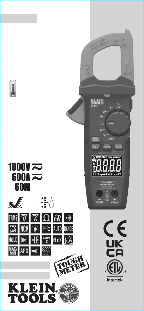
600A AC/DC Auto-Ranging
Digital Clamp Meter
True RMS
Measurement
Technology
• NON-CONTACT
VOLTAGE TESTER
• LOW IMPEDANCE
• DATA & RANGE HOLD
• AUDIBLE CONTINUITY
• DIODE TEST
• CAPACITANCE & FREQUENCY
• TRANSFLECTIVE
REVERSE-CONTRAST DISPLAY
• LIGHTED DIAL
1000V
60M
Ω
600A
CL810
2
m
IP40
-40° – 1832°F
(-40° – 1000°C)
5000573
CAT IV
600V
CAT III
1000V

2 3
GENERAL SPECIFICATIONS
Klein Tools CL810 is an automatically ranging true root mean square
(TRMS) digital clamp-meter that measures AC/DC current via the clamp,
measures AC/DC voltage, resistance, continuity, frequency, inrush,
capacitance, and tests diodes via test-leads, and temperature via a
thermocouple probe. It also features a Low Impedance (LoZ) mode for
identifying and eliminating ghost or stray voltages, transflective reverse-
contrast display, and lighted dial.
• Environment: Indoor: Do not expose to moisture, rain or snow.
• Operating Altitude: 6562 ft. (2000m)
• Relative Humidity: <80% non-condensing
• Operating Temp: 32° to 122°F (0° to 50°C)
• Storage Temp: 14° to 140°F (-10° to 60°C)
• Accuracy: Values stated at 65° to 83°F (18° to 28°C)
• Temp Coefcient: 0.1 × (Quoted Accuracy) per °C above 28°C
or below 18°C, corrections are required when ambient working
temp is outside of Accuracy Temp range
• Auto Power-Off (APO): After 5 minutes of inactivity (unless
disabled)
• Dimensions: 9.06" × 3.47" × 1.65" (230 × 88 × 42 mm)
• Weight: 13 oz. (369 g) including batteries
• Calibration: Accurate for one year
• Standards:
IEC EN 61010-1, 61010-2-032.
Conforms to: UL STD 61010-1, 61010-2-032.
Certied to: CSA STD C22.2 #61010-1, 61010-2-032.
• Pollution degree: 2
• Accuracy: ± (% of reading + # of least significant digits)
• Drop Protection: 6.6 ft. (2m)
• Safety Rating: CAT IV 600V, CAT III 1000V, Class 2,
Double insulation
CAT III: Measurement category III is applicable to test and
measuring circuits connected to the distribution part of the
building’s low-voltage MAINS installation.
CAT IV: Measurement category IV is applicable to test and
measuring circuits connected at the source of the building’s
low-voltage MAINS installation.
• Electromagnetic Environment: IEC EN 61326-1. This
equipment meets requirements for use in basic and controlled
electromagnetic environments like residential properties,
business premises, and light-industrial locations.
Specifications subject to change.
ELECTRICAL SPECIFICATIONS
Function Range Resolution Accuracy LoZ Accuracy
AC
Voltage
(V AC)
600mV 0.1mV ±(1.8% + 8 digits)
±(2.5% + 8
digits)
6.000V 1mV
±(1.0% + 3 digits)60.00V 10mV
600.0V 100mV
1000V 1V ±(1.2% + 5 digits)
DC
Voltage
(V DC)
600mV 0.1mV
±(0.5% + 5 digits)
±(2.0% + 5
digits)
6.000V 1mV
60.00V 10mV
600.0V 100mV ±(0.8% + 3 digits)
1000V 1V ±(1.0% + 3 digits)
Input Impedance: 10MΩ Frequency Range: 50 to 400Hz
Maximum Input: 1000V AC RMS or 1000V DC
NOTE: All AC voltage ranges are specified from 5% to 100% of range.
AC Current
(A AC)
60.00A 10mA ±(2.0% + 8 digits)
600.0A 100mA ±(2.0% + 5 digits)
DC Current
(A DC)
60.00A 10mA ±(2.0% + 8 digits)
600.0A 100mA ±(2.0% + 5 digits)
Frequency Range: 50 to 60Hz
DC
Microamps
(DC µ)
200.0µA 0.1µA ±(1.0% + 5 digits)
Maximum Input: 1000V AC RMS or 1000V DC
Function Range Resolution Accuracy
Resistance
600.0Ω 0.1Ω
±(1.2% + 5 digits)
6.000kΩ 1Ω
60.00kΩ 0.01kΩ
600.0kΩ 0.1kΩ
6.000MΩ 1kΩ
60.00MΩ 10kΩ ±(2.0% + 10 digits)
Maximum Input: 1000V AC RMS or 1000V DC
Capacitance
60.00nF 0.01nF ±(3.5% + 10 digits)
600.0nF 0.1nF
±(3.0% + 5 digits)
6.000µF 0.001µF
60.00µF 0.01µF
600.0µF 0.1µF
6000µF 1µF ±(3.5% + 5 digits)
Maximum Input: 1000V AC RMS or 1000V DC
Temperature
(Fahrenheit)
-40° to 10°F
1
°F
±(1.2% + 7
°F
)
11° to 1832°F
±(1.2% + 6
°F
)
Temperature
(Celsius)
-40° to -12°C
1
°C
±(1.2% + 4
°C
)
-11° to 1000°C
±(1.3% + 3
°C
)
ENGLISH
5000573

4 5
ELECTRICAL SPECIFICATIONS
Function Range Resolution Accuracy
Frequency
(Auto-
Ranging)
1.000Hz to 9.999Hz 0.001Hz
±(1.0% + 5 digits)
99.99Hz 0.01Hz
999.9Hz 0.1Hz
9.999kHz 1Hz
99.99kHz 10Hz
500.00kHz 100Hz
Sensitivity: >2V to 220V RMS
Maximum Input: 1000V AC RMS or 1000V DC
Duty Cycle
1.0% to 99.9%
0.1%
±(1.2% + 2 digits)
Pulse width: >100µs, <100ms Frequency width: 5Hz to 10kHz
Sensitivity: >2V to 220V RMS Maximum Input: 1000V DC or 1000V AC RMS
Inrush
Current
600.0A 100mA ±(3.0% + 8 digits)
Frequency Range: 50 to 60Hz Detection Range: >2A
OTHER MEASUREMENT APPLICATIONS
Maximum Input: 1000V AC RMS or 1000V DC
• Diode Test: Max. 1.5mA, open circuit voltage ~3.2V DC
• Continuity Check: Audible signal <50Ω, test current <1.5mA
• Sampling Frequency: 4 samples per second
• Low Impedence (Low Z): Input impedence >3kΩ,
Max input 1000V AC RMS or 1000V DC RMS
• Auto Power-Off: After ~5 minutes of inactivity
• Overload: "OL" indicated on display, overload protection 1000V in all settings
• Polarity: "-" on display indicates negative polarity
• Display: 3-5/6 digit, 6000 Count LCD
ENGLISH
WARNINGS - GENERAL
To ensure safe operation and service of the meter, follow these instructions.
Failure to observe these warnings can result in severe injury or death.
• Before each use verify meter operation by measuring a known voltage
or current.
• Never use the meter on a circuit with voltages that exceed the category
based rating of this meter.
• Do not use the meter during electrical storms or in wet weather.
• Do not use the meter or test leads if they appear to be damaged.
• Use only with CAT III 1000V/CAT IV 600V rated test leads or better.
• Ensure meter leads are fully seated, and keep fingers away from the
metal probe contacts when making measurements.
• Use caution when working with voltages above 25V AC RMS or 60V DC.
Such voltages pose a shock hazard.
• To avoid false readings that can lead to electrical shock, replace batteries
when a low battery indicator appears.
• Do not attempt to measure resistance or continuity on a live circuit.
• Always adhere to local and national safety codes. Use personal protective
equipment to prevent shock and arc blast injury where hazardous live
conductors are exposed.
• To avoid risk of electric shock, disconnect leads from any voltage source
before removing battery door.
• To avoid risk of electric shock, do not operate meter while battery door is removed.
WARNINGS - NCV FUNCTION
• When NCV Function is initiated, a blinking or steady red glow and an audible
beep indicate voltage present, and the screen will display the corresponding
sensitivity level (1 to 4 bars) when voltage is detected. If no indication, voltage
could still be present.
• Before and after each use of the NCVT, verify operation by testing a known
working circuit that is within the rating of this unit.
• Never assume neutral or ground wires are de-energized. Neutrals in multi-wire
branch circuits may be energized when disconnected and must be retested
before handling.
• The NCV tester WILL NOT detect voltage if:
• The wire is shielded.
• The
operator is not grounded or is otherwise isolated from an effective earth ground.
• The voltage is DC.
• The NCV tester MAY NOT detect voltage if:
• The user is not holding the tester.
• The user is insulated from the tester with a glove or other materials.
• The wire is partially buried or in a grounded metal conduit.
• The tester is at a distance from the voltage source.
• The field created by the voltage source is blocked, dampened, or otherwise
interfered with.
• The frequency of the voltage is not a perfect sine wave between 50 and 60Hz.
• The tester is outside of operation conditions (listed in Specifications section).
• Operation may be affected by differences in socket design and insulation
thickness and type; tester may not be compatible with some types of standard
or tamper resistant (TR) electrical outlets.
• Do not apply to uninsulated hazardous live conductors.
• Detection above 50V is specified under “normal” conditions as specified below.
The tester may detect at a different threshold at different conditions, or may not
detect at all unless:
• The
tip of the tester is within 0.25" of an AC voltage source radiating unimpeded.
• The user is holding the body of the tester with his or her bare hand.
• The user is standing on or connected to earth ground.
• The air humidity is nominal (50% relative humidity).
• The tester is held still.
Tuotetiedot
Merkki: | Klein Tools |
Kategoria: | Mittauslaitteet |
Malli: | CL810 |
Tarvitsetko apua?
Jos tarvitset apua merkille Klein Tools CL810 esitä kysymys alla ja muut käyttäjät vastaavat sinulle
Mittauslaitteet Klein Tools Käyttöohjeet
21 Tammikuuta 2025
20 Tammikuuta 2025
14 Tammikuuta 2025
14 Tammikuuta 2025
10 Tammikuuta 2025
10 Tammikuuta 2025
10 Tammikuuta 2025
10 Tammikuuta 2025
31 Joulukuuta 2025
26 Joulukuuta 2024
Mittauslaitteet Käyttöohjeet
- Mittauslaitteet Uni-T
- Mittauslaitteet Kyoritsu
- Mittauslaitteet Extech
- Mittauslaitteet Milwaukee
- Mittauslaitteet Siglent
- Mittauslaitteet Fluke
- Mittauslaitteet Chauvin Arnoux
- Mittauslaitteet Angler
- Mittauslaitteet Gossen Metrawatt
- Mittauslaitteet Mitutoyo
- Mittauslaitteet Phoenix Contact
- Mittauslaitteet Crowcon
- Mittauslaitteet Senseca
- Mittauslaitteet Clean Air Optima
- Mittauslaitteet CEM
Viimeisimmät Mittauslaitteet Käyttöohjeet
3 Huhtikuuta 2025
3 Huhtikuuta 2025
3 Huhtikuuta 2025
3 Huhtikuuta 2025
3 Huhtikuuta 2025
3 Huhtikuuta 2025
3 Huhtikuuta 2025
3 Huhtikuuta 2025
3 Huhtikuuta 2025
3 Huhtikuuta 2025