Hobbywing XeRun XR10 PRO DR Käyttöohje
Hobbywing Radio-ohjattavat lelut XeRun XR10 PRO DR
Lue alta 📖 käyttöohje suomeksi merkille Hobbywing XeRun XR10 PRO DR (2 sivua) kategoriassa Radio-ohjattavat lelut. Tämä opas oli hyödyllinen 39 henkilölle ja sai 4.7 tähden keskimäärin 6 käyttäjältä
Sivu 1/2
08
07
06
05
02
01
03
04
ATTENTION
This is an extremely powerful brushless motor system. For your safety and the safety of
those around you, we strongly recommend removing the pinion gear attached to the
motor before performing calibration and programming functions with this system. It is
also advisable to keep the wheels in the air when you turn on the ESC.
• Powerful hardware and software, designed for Drag Racing.
• Factory standard 10AWG silicone wires and super large capacitor module,everything is ready.
• RPM limit by throttle, Boost start rpm and end rpm are all finely adjustable,meeting the precise adjustment of the throttle by the driver.
• Multiple protection functions: low-voltage cutoff protection, ESC and motor thermal protection, and fail safe.
• The data recording function utilizes the OTA Bluetooth module to view various running data of the power system in the HW LINK App on mobile phones, making it easier for drivers to analyze the operation of
the power system.
• Firmware upgrade via Hobbywing LCD Pro program box or OTA Programmer (item sold separately).
Option 2: Traditional
This brake mode is the same as to other standard ESCs, the brake force is stronger.
Option 3: Hybrid
The ESC switches the brake mode between Linear and Traditional as per the vehicle speed to prevent the slide (between tires and track) from affecting the braking effect.
Note: Please select the right mode for your vehicle as per the track condition, motor performance, and etc.
4A. Boost Timing
It is effective within the whole throttle range; it directly affects the car speed on straightaway and turns.The actual boost timing during the operation is adjusted based on the parameter item 4B. The Boost
Timing is not constant but variable.
4B. Boost Timing Activation
Option 1: RPM
In RPM mode, the ESC adjusts the Boost Timing dynamically as per the motor speed (RPM). The actual Boost Timing is 0 when the RPM is lower than the Boost Start RPM. The Boost Timing changes as per the
RPM when the RPM change is between the Boost Start RPM and the Boost End RPM. For example, if the Boost Timing is set to 5 degrees and the Boost Start RPM is 10000, the Boost End RPM is 15000. The
Boost Timing corresponds to different RPM is shown below. When the RPM is higher than the Boost End RPM, the actual Boost Timing is the value you had previously set.
1A. Running Mode
Option 1: Forward with Brake
Racing mode. It has only forward and brake functions.
Option 2: Forward/ Reverse with Brake
This option is known to be the “training” mode with “Forward/ Reverse with Brake” functions. The vehicle only brakes on the first time you push the throttle trigger to the reverse/brake position.If the motor stops
when the throttle trigger return to the neutral position and then re-push the trigger to reverse position,the vehicle will reverse,if the motor does not completely stop,then your vehicle won’t reverse but still brake,you
need to return the throttle trigger to the neutral position and push it to reverse again.This method is for preventing vehicle from being accidentally reversed.
Option 3: Forward and Reverse
The motor will reverse immediately when the throttle trigger is pushed to reverse position.This mode is generally used in special vehicles.
1B. Max. Reverse Force
The reverse force of the value will determine its speed. For the safety of your vehicle, we recommend using a low amount.
1C. Cutoff Voltage
Sets the voltage at which the ESC lowers or removes power to the motor in order to either keep the battery at a safe minimum voltage (for LiPo batteries). The ESC monitors the battery voltage all the time, it will
reduce the power to 50% (in 2 seconds) and cut off the output 40 seconds later when the voltage goes below the cutoff threshold. The RED LED will flash a short, single flash that repeats (, , ) to indicate the ☆☆☆
low-voltage cutoff protection is activated. Please set the “Cutoff Voltage” to “Disabled” or customize this item if you are using NiMH batteries.
Option 1: Disabled
The ESC does not cut the power off due to low voltage. We do not recommend using this option when you use any LiPo battery as you will irreversibly damage the product. You need to select this option when you
are using a NiMH pack.
Option 2: Auto
The ESC calculates the corresponding cutoff voltage for the battery shall be 7.0V.
Option 3: Customized
The customized cutoff threshold is a voltage for the whole battery pack (adjustable from 3.0V to 7.4V).
1D. ESC Thermal Protection
The output from the ESC will be cut off with the value you have preset.
The GREEN LED flashes (, , ) when the ESC temperature reaches to the preset value. The output will not resume until the ESC temperature gets down. ☆☆☆
Warning! Please do not disable this function unless you’re in a competition. Otherwise the high temperature may damage your ESC and even your motor.
1E. Motor Thermal Protection
The GREEN LED flashes (, , ) when the motor temperature reaches to the preset value. The output will not resume until the motor temperature gets down. ☆☆☆☆☆☆
Warning! Please do not disable this function unless you’re in a competition. Otherwise the high temperature may damage your motor and even your ESC. For non-Hobbywing motor, the ESC may
activate the motor thermal protection too early or late due to the differences in the temperature sensors. In this case, please disable this function and monitor the motor temperature manually.
1F. BEC Voltage
BEC voltage can be adjusted between 6.0-7.4V. 6.0V is applicable to common servo. If use high-voltage servo , set to higher voltage according to voltage marking of servo.
1G. Motor Rotation/Direction
With the motor shaft faces you (the rear end of the motor is away from you), increase the throttle input, the motor (shaft) will rotate in the CCW/CW direction if the “Motor Rotation / Direction” set to “CCW/CW”.
Generally, the vehicle runs forward when the motor (shaft) rotates in the CCW direction. However, some vehicles only run forward when the motor rotates in the CW direction due to the different chassis design. In
that case, you only need to set the “Motor Rotation/Direction” to “CW).
2A. Throttle Rate Control
This item is used to control the throttle response. The higher the throttle rate,the more aggressive the throttle will be applied. A suitable rate can help driver to control the vehicle properly during the starting-up process.
2B. Throttle Curve
The throttle curve parameter reconciles the position of the throttle trigger and the actual ESC throttle output. It is linear by default and we can change it to non-linear via adjusting the throttle curve. For example, if
adjust it to +EXP, the throttle output at the early stage will be higher (than the output when the curve is linear); if it is adjusted to –EXP, the throttle output at the early stage will be lower (than the output when the
curve is linear).
2C. Neutral Range
This parameter adjusts the range of the throttle neutral area to suit different transmitters and driver habits. If the neutral position of the transmitter is unstable,causing the car to move slowly forward or backward, or
have difficulties calibrating the neutral range, the setting can be raised to correct the issue.
2D. Initial Throttle Force
It also called as minimum throttle force. You can set it according to wheel tire and traction. If the ground is slippery, please set a small throttle force. Some motors have strong cogging effect with lower FDR ,if there is
any cogging with very light throttle input,you can try to increase the initial throttle force.
2E. PWM Drive Frequency
The acceleration will be more aggressive at the initial stage when the drive frequency is low; a higher drive frequency is smoother but this will create more heat to the ESC.If set this item to "Customized", then the
PWM frequency can be adjusted to a variable value at any 0-100% throttle input, Please choose the frequencies as per the actual test results of your vehicles.
2F. Softening Value
It allows users to fine-tune the bottom end, change the driving feel, and maximize the driving efficiency at different track conditions. The higher the "Softening Value ", the milder the bottom end. In Modified
class, drivers often feel the power of the bottom end is too aggressive. Little throttle input usually brings too much power to the car and make it hard to control at the corners, this is HOBBYWING's solution to help
bottom end traction.
You can increase the motor mechanical timing accordingly after you set the softening value. Every time you increase the softening value by 5 degrees, you can increase the mechanical timing by 1 degree. Note:
For example, if you set the softening value to 20 degrees, then you can increase the mechanical timing by 4 degrees. Please note that you will never increase the mechanical timing by over 5 degrees.
2G. Softening Range
It's the range to which "Softening Value” starts and ends. For example, 0% to 30% will be generated when the user pre-programs the "Softening Range" at a value of 30%.
2H. RPM Limit By Throttle
This parameter refers to the maximum motor rpm allowed within the throttle range, associated with item 2I (RPM Limit Range).
2I. RPM Limit Range
Refers to the throttle range corresponding to the limited motor rpm. For example,if the item 2H (RPM Limit By Throttle) is set to 20000,and this item is set to 30%,it means that the maximum motor rpm limited within
the 30% throttle range is 20000.
2J. Max RPM Limit
Refers to the maximum motor rpm limit with the whole throttle range.
3A. Drag Brake
It is the braking power produced when releasing from the throttle to neutral position. This is to simulate the slight braking effect of a neutral brushed motor while coasting. It’s not recommended for buggy and
monster truck.
(Attention! Drag brake will consume more power and heat will be increased, apply it cautiously.)
3B. Max. Brake Force
This ESC provides proportional braking function; the braking effect is decided by the position of the throttle trigger. It sets the percentage of available braking power when full brake is applied. Large amount
will shorten the braking time but it may damage your pinion and spur.
3C. Brake Rate Control
It’s adjustable from 1 to 20 (step: 1). The larger the setting value, the greater the brake rate, that is, the faster the braking. A suitable rate can aid the driver to brake his vehicle correctly. Generally, you can set it to a
high value to have a quick brake response.
3D. Brake Frequency
The brake force will be larger if the frequency is low; you will get a smoother brake force when the value is higher.If set this item to "Customized", then the brake frequency can be adjusted to a variable value at any
0-100% throttle input. Please choose the frequencies as per the actual test results of your vehicles.
3E. Brake Control
Option 1: Linear
Hobbywing has recommended using this mode under all circumstances. The braking effect is a bit weaker in this mode than in Traditional brake mode, but it’s easy to control and brings great control feel.
CAUTIONS
Thank you for purchasing this HOBBYWING product! Please read this declaration carefullybefore
use, once you use the product,we will assume that you have read and agreed with all the
content.Brushless power systems can be very dangerous and any improper use may cause
personal injury and damage to the product and related devices, so please strictly follow the
instruction during installation and use.Because we have no control over the use,installation, or
maintenance of this product, no liability may be assumed for any damages or losses resulting
from the use of the product. We do not assume responsibility for any losses caused by
unauthorized modifications to our product. We have the right to modify our product design,
appearance, features and usage requirements without notification. We, HOBBYWING, are only
responsible for our product cost and nothing else as result of using our product.Regarding the
possible semantic different between two different versions of declaration, for users in mainland
China, please take the Chinese version as standard; for users in other regions, please take the
English version as standard.
High-Performance Product Notice:
Due to the specialized nature and high-performance requirements of the intended
applications, this product has been engineered to operate beyond typical standards.
Consequently, it does not follow standard warranty service options for damage incurred
during operation. Please review the warranty section of the website for terms,
conditions and further details.
ATTENTION
2
Option 2: Auto
In Auto mode, the ESC adjusts the Boost Timing dynamically as per the throttle amount. Only at full throttle, the actual Boost Timing is the value you had previously set.
Option 3: Timing Rate
In this mode, the boost timing is turned on according to the value set by the parameter item 4E(Boost Increase Rate).
4C. Boost Start RPM
This item defines the RPM at which Boost Timing is activated. For example, when the Boost Start RPM is set to 5000, the ESC will activate the corresponding Boost Timing when the RPM goes above 5000.
The specific value is determined by the Boost Timing and the Boost End RPM you had previously set.
4D. Boost End RPM
This item defines the RPM at which Boost Timing (you specifically set) is applied. For example, when Boost Timing is set to 10 degrees and the Boost End RPM to 15000, the ESC will activate the Boost Timing
of 10 degrees when the RPM goes above 15000. The ESC will adjust the Boost Timing accordingly as per the actual RPM when the RPM goes below 15000.
4E. Boost Increase Rate
Used to set the speed of the Boost response.Release a certain degree every 0.1 seconds until fully released. For example, if the parameter is set to 4 °/0.1s and the Boost timing is set to 40 degrees, the Boost
timing will be released at a speed of 4 degrees/0.1s, and after 1 second, all 40 degrees will be released.
5A. Turbo Timing
This item is adjustable from 0 degree to 64 degrees, the corresponding turbo timing (you set) will initiate at full throttle. It’s usually activated on long straightaway and makes the motor unleash its maximum potential.
5B. Turbo Delay
When “TURBO DELAY” is set to “INSTANT”, the Turbo Timing will be activated right after the throttle trigger is moved to the full throttle position. When other value(s) is applied, you will need to hold the
throttle trigger at the full throttle position (as you set) till the Turbo Timing initiates.
5C. Turbo Increase Rate
This item is used to define the “speed” at which Turbo Timing is released when the trigger condition is met. For example, “3 degs/0.1sec” refers to the Turbo Timing of 6 degrees that will be released in 0.1
second. Both the acceleration and heat is higher when the “Turbo increase rate” is of a larger value.
5D. Turbo Decrease Rate
After the Turbo Timing is activated and the trigger condition turns to not be met (i.e. vehicle slows down at the end of the straightaway and gets into a corner, full throttle turns to partial throttle, the trigger
condition for Turbo Timing turns to be not met), if you disable all the Turbo Timing in a moment, an obvious slow-down like braking will be felt and cause the control of vehicle to become bad. If the ESC can
disable the Turbo Timing at some “speed”, the slow-down will be linear and the control will be improved.
Warning!Boost Timing & Turbo Timing can effectively improve the motor efficiency; they are usually used in competitions. Please take some time to read this manual and then set these two items carefully,
monitor the ESC & motor temperatures when you have a trial run and then adjust the Timing and FDR accordingly as aggressive Timings and FDR may cause your ESC or motor to be burnt.
1. During the Start-up Process
• The RED LED turns on solid indicating the ESC doesn’t detect any throttle signal or the throttle trigger is at the neutral position.
• The GREEN LED flashes rapidly indicating the neutral throttle value stored on your ESC may be different from the current value stored on the transmitter. When this happens, re-calibrate the throttle range.
2. In Operation
• The RED LED will blink when the throttle trigger is in the neutral zone, it is Blinky Mode,which means the timing value is zero.If the timing value is not zero,the RED LED will turn on solid.
• The GREEN LED blinks when your vehicle runs forward. The GREEN LED turns solid when pulling the throttle trigger to the full (100%) throttle endpoint.
• The GREEN LED blinks when you brake your vehicle. The GREEN LED turns solid when pushing the throttle trigger to the full brake endpoint and setting the “maximum brake force” to 100%.
• The GREEN LED blinks when you reverse your vehicle. The GREEN LED turns solid when pushing the throttle trigger to the full reverse endpoint and setting the “reverse force” to 100%.
3. When Some Protection is Activated
• The RED LED flashes a short, single flash and repeats “, , ” indicating the low voltage cutoff protection is activated.☆☆☆
• The GREEN LED flashes a short, single flash and repeats “, , ” indicating the ESC thermal protection is activated.☆☆☆
• The GREEN LED flashes a short, double flash and repeats “, , ” indicating the motor thermal protection is activated.☆☆☆☆☆☆
• The RED & GREEN LEDS flash a short, single flash and repeats “, , ” at the same time indicating the drive mode has been automatically switched to sensorless mode from senored mode because of ☆☆☆
abnormal sensor signal when pairing the ESC with a sensored motor.
RPM (Motor Speed)
Actual Boost Timing
<10000
0 Degree
10001-11000
1 Degree
11001-12000
2 Degrees
12001-13000
3 Degrees
13001-14000
4 Degrees
14001-15000
5 Degrees
>15000
5 Degrees
5
4
External Programming
Port for Connecting
Program Card or OTA
Programmer.
In order to make one firmware applicable to all different racing conditions, there are ten “easy-to-select” preset modes. Users are able to change the settings of the modes provided (and rename those modes) as
per the control feel, track, and etc. For example, the profile name can be changed to “TITI2024_MOD_4.5” to indicate the race was ran with a 4.5T motor at 2024 TITC. This can be saved for future reference as
well.
3
Cont./Peak Current
Motor Type
Applications
Recommended Motor
LiPo Cells
BEC Output
Cooling Fan
Size
Weight
Programming Port
200A / 1200A
Sensored Brushless Motors
1/10th Drag Racing
3652/3662(540/550) size motors KV9800≤
2S Lipo
5-7.4V Adjustable, Continuous Current of 5A
Powered by the stable BEC voltage
37.7x37.2x33.2mm(w/Fan&Fan Shroud)
137g(w/ wires)
Independent programming interface
ModelXERUN XR10 PRO DR
USER MANUAL
XERUN XR10 Pro DR
Brushless Electronic Speed Controller
1
Set throttle range
With the throttle trigger in the neutral
position and press the SET button.
Press the SET
button and the
Green LED
flashes once.
Move the throttle trigger to the full throttle
and press the SET button.
Press the SET button
and the Green LED
flashes twice.
Move the throttle trigger to the full brake
and press the SET button.
Press the SET button
and the Green LED
flashes three
times.
Hold the SET
button.
Turn on the
switch
Release the SET
button once the LED
flashes.
2. Turn off the ESC. Hold the SET button and turn on the ESC, the RED LED on the ESC starts to flash (the motor beeps at the same time), and then release the SET button.
Note : Beeps from the motor may be low sometimes, and you can check the LED status instead.
1. Turn on the transmitter, ensure all parameters (D/R,
Curve, ATL) on the throttle channel are at default
(100%). For transmitter without LCD, please turn the
knob to the maximum, and the throttle “TRIM” to 0.
Please also turn the corresponding knob to the
neutral position. This step can be skipped if the
radio's settings are default.
SHENZHEN HOBBYWING TECHNOLOGY Co., LTD. · 101-402 Building 4, Yasen Chuangxin Hi-tech Industrial Park, 8 Chengxin Road, Baolong Industrial Town, Longgang District, Shenzhen, China.
August 22, 2024
HW-SMA542DUL00
20240822
• To avoid short circuits, ensure that all wires and connections are well insulated before connecting the ESC to related devices.
• Ensure all devices in the system are connected correctly to prevent any damage to the system.
• Read the manuals of all the items being used in the build.Ensure gearing,setup,and overall install is correct and reasonable.
• Please use a soldering iron with the power of at least 60W to solder all input / output wires and connectors.
• Do not hold the vehicle in the air and rev it up to full throttle, as rubber tires can “expand” to extreme size or even explode and cause serious injury.
• Stop usage if the casing of the ESC exceeds 90/ 194 as this may cause damage to both the ESC and motor. Hobbywing recommends setting the “ESC Thermal Protection” to 105/ 221 (this refers to the ℃ ℉℃ ℉
internal temperature of the ESC).
• The battery must be disconnected after use.There is a small draw even when the system is off,and will eventually fully drain the battery.This may cause damage to the ESC, and will NOT BE COVERED UNDER
WARRANTY.
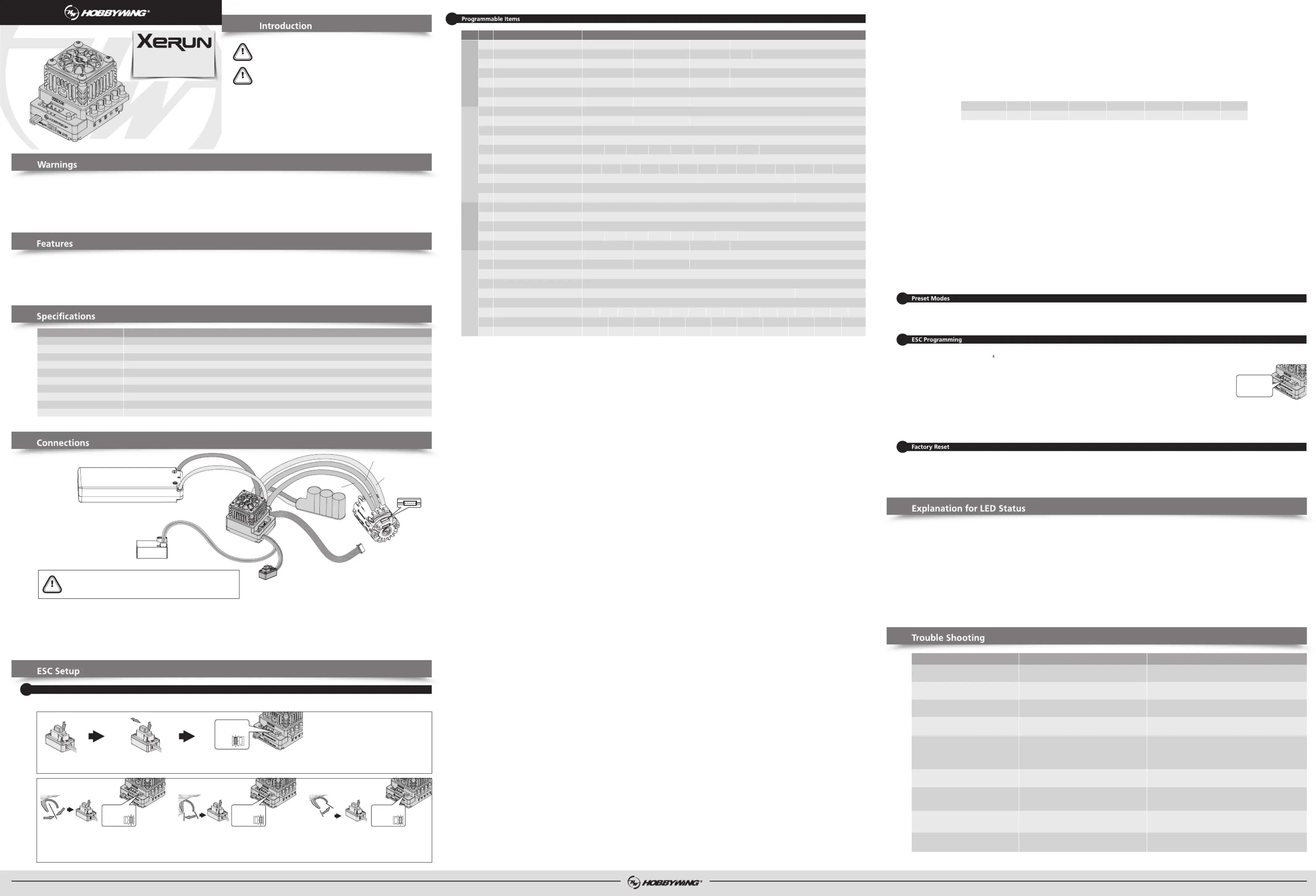
1. Motor Connetion
Sensored motor connection MUST connect A from the ESC to A on the motor, B to B, and C to C, with the sensor wire connected any variation of the motor to ESC connections may cause damage.
Note: If the motor direction is reversed, change the parameter item “Motor Rotation” to achieve the correct setting.
2. Receiver Connetion
The throttle control cable on the ESC has to be plugged into the throttle (TH) channel on the receiver. The throttle control cable has an output voltage of 5-7.4V to the receiver and steering servo, hence, no
separate battery can be connected to the receiver. Otherwise, your ESC may be damaged.If additional power is required, disconnect the red wire on the throttle plug from the ESC.
3. Battery Connetion
Proper polarity is essential. Please ensure positive (+) connects to positive (+), and negative (-) connects to negative (-) when plugging in the battery! If the connection is reversed,the ESC will be damaged
and will not be covered by the warranty.
Note: The default firmware for ESC is Blinky Mode(zero timing),so there is no timing options (4A-5D).If you need to use the timing,you can update the firmware with the timing options through the
mobile app or computer.
You must calibrate throttle range when you begin to use a new ESC, the transmitter has been replaced,or the Throttle TRIM have been adjusted, otherwise the ESC cannot work correctly. We strongly
recommend users to use the “Fail Safe” function on the radio system and set (F/S) to “Output OFF” or “Neutral Position”.The throttle calibration steps are below:
3. Set the neutral point, the full throttle endpoint and the full brake endpoint.
• Leave transmitter at the neutral position, press the SET button, the GREEN LED flashes 1 time and the motor beeps 1 time to accept the neutral position.
• Pull the throttle trigger to the full throttle position, press the SET button, the GREEN LED blinks 2 times and the motor beeps 2 times to accept the full throttle endpoint.
• Push the throttle trigger to the full brake position, press the SET button, the GREEN LED blinks 3 times and the motor beeps 3 times to accept the full brake endpoint.
4. The motor can be started after the ESC/Radio calibration is complete.
• Restore the default values with a multifunction LCD program box pro
After connecting the program box to the ESC, Click onParameter Settingsand select theReset Parameters to restore the factory settings.【】【】
• Restore the default values with a OTA Programmer (& HW Link App)
After connecting the OTA Programmer to the ESC, open the HOBBYWING HW Link App on your smart phone, select “Parameters” followed by “Factory Reset” to reset the ESC.
The default/popular motor rotation direction does
not match your car frame.
1. The receiver was influenced by some foreign interference;
2. The ESC entered the LVC protection;
3. The ESC entered the thermal shutdown protection.
1. The throttle neutral position on your transmitter
was actually in the braking zone;
2. Set the “Running Mode” improperly;
3. The ESC was damaged.
1. The (ESC-to-motor) wiring order was incorrect
2. Some soldering between the motor and the ESC was not good;
3. The ESC was damaged (some MOSFETS were burnt).
Adjust the parameter "Motor Rotation".
1. Check all devices and try to find out all possible causes, and check the
transmitter’s battery voltage;
2. The RED LED keeps flashing indicating the LVC protection is activated,
please replace your pack;
3. The GREEN LED keeps flashing indicating the thermal protection is
activated, please let your ESC cool down before using it again.
1. Recalibrate the throttle neutral position;
2. Set the “Running Mode” to “Fwd/Rev with Brk “;
3. Contact the distributor for repair or other customer service.
1. Check the wiring order;
2. Check all soldering points, please re-solder if necessary;
3. Contact the distributor for repair or other customer service.
1. Change another pack with great discharging capability;
2. Change a low-speed motor, or increase the FDR;
3. Set the Throttle Rate Control to a low level.
1. Check if the sensor cable is loose or poor contact issue exists;
2. Hall sensor inside the motor or the ESC is damaged.
The vehicle is going in the reversed direction
when the forward throttle is applied.
The motor stuttered but couldn’t start.
The vehicle could run forward (and brake),
but could not reverse.
The motor got stuck or stopped when increasing
the throttle during the starting-up process.
The RED & GREEN LEDS on the ESC flashed rapidly
at the same time when the throttle trigger was at
the neutral position.
The motor suddenly stopped or significantly
reduced the output in operation.
1. Poor discharging capability of the pack;
2. The RPM of the motor was too high, or the FDR
was too low;
3. The Throttle Rate Control is set too high.
(When pairing with a sensored motor) the ESC
automatically switched to sensorless mode
when it detected incorrect signal from Hall sensor.
TroublesSolutionsPossible Causes
1. The battery voltage was not output to the ESC.
2. The ESC switch was damaged.
The battery voltage is not within the normal range.
1. The ESC does not detect the throttle signal.
2. The neutral point of the ESC does not match
with the transmitter.
1.Check whether there is poor welding of power input gate and reweld it.
2. Replace the switch.
Check the battery voltage.
1. Check whether the throttle wire and the channel is plugged correctly,
and whether the transmitter is turned on.
2. Move the throttle trigger to the neutral point and recalibrate the throttle range.
The motor cannot start and emit Bi-Bi-, Bi-Bi-,
with the green LED flashing (the interval between
the Bi-Bi- and Bi-Bi- is 1 seconds)
Power on and Red LED flashes rapidly.
The motor does not rotate.
The LED isn’t on and the motor cannot start.
Battery
Motor
A
Electronic Speed Controller
C
Sensor port of motor
Sensor wire
Switch
Receiver
B
Parameter ValuesSectionItem
Programmable Items
Forward and ReverseForward/ Reverse with Brake
General SettingThrottle ControlBrake ControlTiming
1ARunning ModeForward with Brake
3.0-7.4V Adjustable (Step: 0.1V)Auto (3.5V/Cell)1CCutoff VoltageDisabled
75%50%
1B
Max. Reverse Force
25%
100%
125/257℃℉
105/221℃℉1D
ESC Thermal Protection
Disabled
3%-10% Adjustable (Step: 1%)2C
Neutral Range
1%-100% Adjustable (Step: 1%)2D
Initial Throttle Force
HybridTraditional
3E
Brake ControlLinear
RPMTiming Rate
4B
Boost Timing ActivationAuto
4K2K2EPWM Drive Frequency1K
1F
BEC Voltage
5.0V-7.4V Adjustable (Step:0.1V)
2A
Throttle Rate Control
1-30 Adjustable (Step: 1)
2FSoftening Value0-30° Adjustable (Step: 1°)
2HRPM Limit By Throttle300000RPM5000RPM-180000RPMStep5000RPM(:)
2JMax RPM Limit300000RPM50000RPM-225000RPMStep5000RPM(:)
Instant()(:)1°-32°/ 0.1sStep1°
2IRPM Limit Range0%-90%Step10%(:)
3A
Drag Brake Force
0%-100% Adjustable (Step: 1%)
3B
Max. Brake Force
0%-100% Adjustable (Step: 1%)
4A
Boost Timing
0-64° Adjustable (Step: 1°)
4C
Boost Start RPM
2000-120000RPM (Step: 1000RPM)
5A
Turbo Timing
0-64° Adjustable (Step: 1°)
4D
4E
Boost End RPM
Boost Increase Rate
10000RPM-200000RPM Step: 1000RPM(10000-100000),2000RPM(100000-200000)
3C
Brake Rate Control1-20 Adjustable (Step: 1)
125/257℃℉
105/221℃℉1E
Motor Thermal Protection
Disabled
CW
1G
Motor RotationCCW
Customized
2B
Throttle CurveLinear
8K12K16K24K32K
Customized
2K1K3D
Brake Frequency
0.5K4K8K12K
16K
30deg/0.1s
20%10%2G
Softening Range
0%25%30%35%40%45%50%55%60%65%70%75%
0.1s0.05s
Instant1deg/0.1s2deg/0.1s3deg/0.1s5deg/0.1s8deg/0.1s12deg/0.1s16deg/0.1s20deg/0.1s25deg/0.1s
5BTurbo DelayInstant0.15s0.2s0.25s0.3s0.35s0.4s0.45s0.5s0.6s0.7s0.8s0.9s1.0s
5CTurbo Increase Rate
30deg/0.1sInstant1deg/0.1s2deg/0.1s3deg/0.1s5deg/0.1s8deg/0.1s12deg/0.1s16deg/0.1s20deg/0.1s25deg/0.1s5DTurbo Decrease Rate
Customized
1. Program your ESC with a multifunction LCD program box pro
Connect the interface marked with "- + " on the esc to the interface marked with "ESC" on the program box using a separate programming cable(a cable with JR plugs at both ends included in the program
box packaging), then connect the esc to the battery and turn it on. Click on Parameter Settings to set the esc.【】
2. Using the OTA Programmer for parameter settings
Insert the programming cable of the OTA Programmer into the programming interface of the esc, and use your phone to install the HW Link APP to set the esc.
3. Read the running data of esc
1) Click on theData recordon the homepage of the LCD box pro to read the four extreme values of the highest temperature of the esc, the highest temperature of 【】
the motor, the lowest voltage of the battery, and the highest rpm of the motor during the operation of the esc.
2) By using the OTA Bluetooth module, you can view the extreme values recorded above, real-time data, and historical data (curve chart) under theData Logmenu 【】
in the HW LINK App on your phone.
4. Upgrade of firmware for esc
1) Using the LCD box pro or OTA programmer, download and install the HW LINK App on your phone,click on theFirmware Updatebutton on the APP homepage to upgrade the firmware of the esc.【】
2) Connect to the computer through the LCD box pro, download and install Hobbywing USB LINK software on the computer, and use this software to upgrade the firmware for esc.
Attention: After the firmware update is completed, it is necessary to reset the parameters in theParametersinterface in order to display the corresponding parameters of the firmware 【】
correctly.
Tuotetiedot
| Merkki: | Hobbywing |
| Kategoria: | Radio-ohjattavat lelut |
| Malli: | XeRun XR10 PRO DR |
Tarvitsetko apua?
Jos tarvitset apua merkille Hobbywing XeRun XR10 PRO DR esitä kysymys alla ja muut käyttäjät vastaavat sinulle
Radio-ohjattavat lelut Hobbywing Käyttöohjeet

29 Maaliskuuta 2025
29 Maaliskuuta 2025
28 Maaliskuuta 2025
28 Maaliskuuta 2025
27 Maaliskuuta 2025
27 Maaliskuuta 2025
27 Maaliskuuta 2025
27 Maaliskuuta 2025
27 Maaliskuuta 2025
27 Maaliskuuta 2025
Radio-ohjattavat lelut Käyttöohjeet
Viimeisimmät Radio-ohjattavat lelut Käyttöohjeet
31 Maaliskuuta 2025
30 Maaliskuuta 2025
30 Maaliskuuta 2025
30 Maaliskuuta 2025
30 Maaliskuuta 2025
30 Maaliskuuta 2025
29 Maaliskuuta 2025
29 Maaliskuuta 2025
29 Maaliskuuta 2025
29 Maaliskuuta 2025