Elan Caputo 84321 Käyttöohje
Lue alta 📖 käyttöohje suomeksi merkille Elan Caputo 84321 (3 sivua) kategoriassa Helpotus. Tämä opas oli hyödyllinen 49 henkilölle ja sai 4.5 tähden keskimäärin 2 käyttäjältä
Sivu 1/3
For warranty informaon please visit: kichler.com/warranty
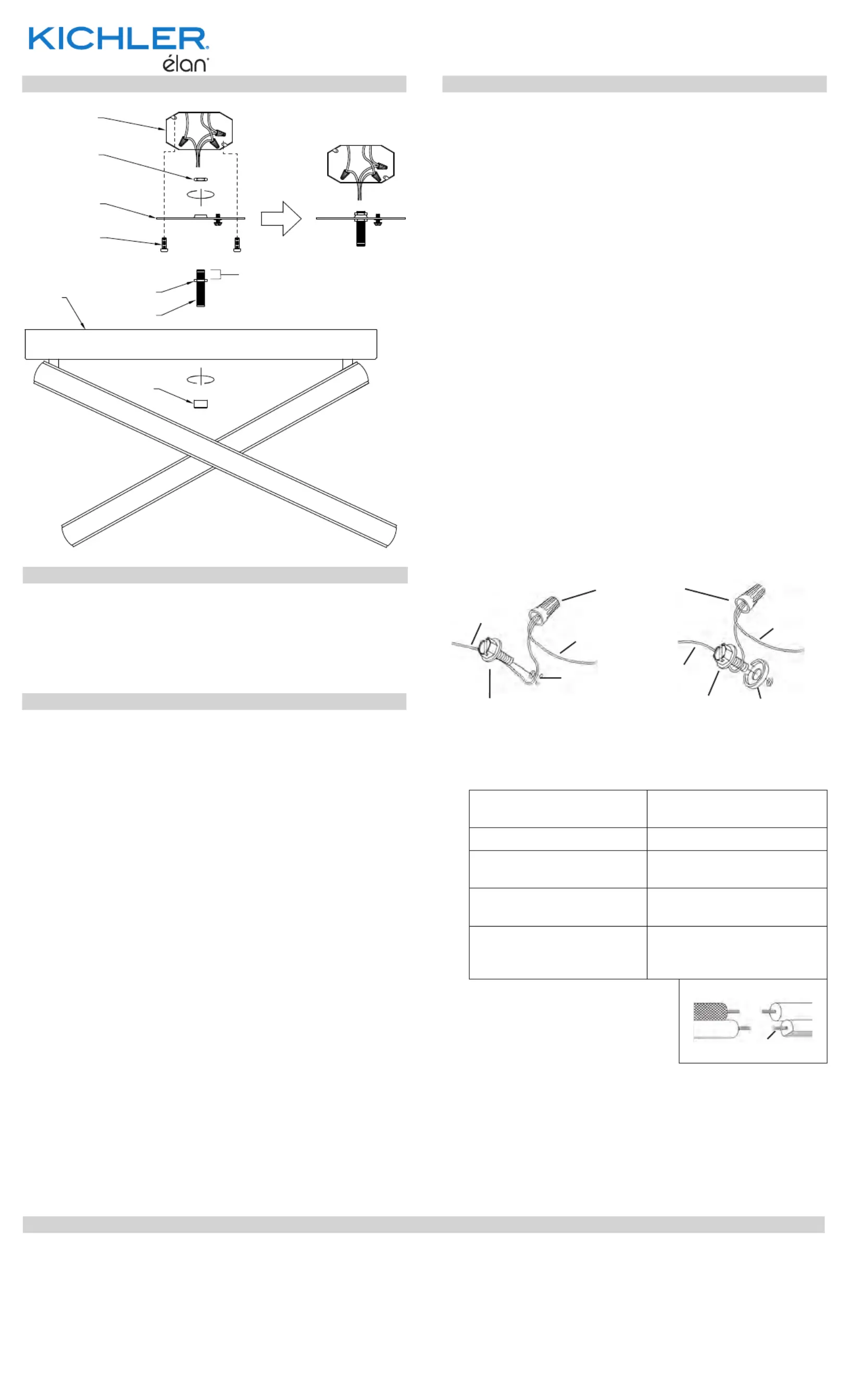
Fixture Diagram
Parts List
Cauons
CAUTION – RISK OF SHOCK –
Disconnect Power at the main circuit breaker panel or main
fusebox before starng and during the installaon.
WARNING:
This xture is intended for installaon in accordance
with the Naonal Electrical Code (NEC) and all local code
specicaons. If you are not familiar with code requirements,
installaon by a cered electrician is recommended.
DIMMING:
This LED xture is compable with most standard
incandescent dimmers, LED dimmers, and electronic low
voltage dimmers.
For opmal performance, an electronic low voltage dimmer
should be used.
See kichler.com/dimming for a list of compable dimmers.
CLEANING:
• Always be certain that electric current is turned o before
cleaning.
• Only a so damp cloth should be used. Harsh cleaning
products may damage the nish.
[A] Outlet Box
[B] Lockup Knob
[C] Hexnut
[D] Mounting
Strap
[E] Canopy
[F] Strap
Mounting
Screw
[G] Threaded
Pipe
1) Take threaded pipe[G] from parts bag and screw on
hexnut[C] a minimum of 13 mm (1/2”) as shown.
2) Screw threaded pipe into mounng strap unl hexnut [D]
prevents the pipe from screwing any further. Mounng
strap must be posioned with extruded thread facing
into outlet box as shown. Threaded pipe must [A]
protrude out the back of mounng strap far enough
to fully engage second hexnut. If necessary, adjust the
posion of rst hexnut on threaded pipe to ensure full
engagement of second hexnut.
3) Screw second hexnut onto end of threaded pipe
protruding from back of mounng strap. Hexnut should
be screwed down onto threaded pipe unl mounng
strap prevents the hexnut from screwing any further.
4) Aach mounng strap[D] to outlet box[A] using the
strap mounng screws. Mounng strap can be [F]
adjusted to suit posion of xture.
5) Grounding instrucons: (See Illus. a or b).
a) On xtures where mounng plate is provided with a
hole and two raised dimples, wrap ground wire from
outlet box around green ground screw, and thread
into hole.
b) On xtures where a cupped washer is provided,
aach ground wire from outlet box under cupped
washer and green ground screw, and thread into
mounng plate.
If xture is provided with ground wire, connect xture
ground wire to outlet box ground wire with wire
connector aer following the above steps. Never connect
ground wire to black or white power supply wires.
6) Make wire connecons. Reference chart below for
correct connecons and wire accordingly.
Connect Black or Red
Supply Wire to:
Connect White Supply
Wire to:
BlackWhite
*Parallel cord (round &
smooth)
*Parallel cord (square &
ridged)
Clear, Brown, Gold or
Black without Tracer
Clear, Brown, Gold or Black
with Tracer
Insulated wire (other
than green) with copper
conductor
Insulated wire (other
than green) with silver
conductor
*Note: When parallel wire (SPT
1 & SPT 2) are used. The neutral
wire is square shaped or ridged
and the other wire will be round
in shape or smooth (See illus.)
Neutral Wire
7) Raise xture to ceiling, carefully passing threaded pipe
aached to mounng strap through center hole in
canopy[E].
8) Screw lockup knob onto threads protruding through [B]
hole in center of canopy.
GREEN GROUND
SCREW
CUPPED
WASHER
OUTLETBOX
GROUND
FIXTURE
GROUND
DIMPLES
WIRE CONNECTOR
OUTLETBOX
GROUND
GREEN GROUND
SCREW
FIXTURE
GROUND
a
b
Installaon Instrucons
This device complies with part 15 of the FCC Rules. Operaon is subject to the following two
condions:
1) This device may not cause harmful interference, and
2) This device must accept any interference received, including interference that may cause
undesired operaon.
Note: This equipment has been tested and found to comply with the limits for a Class B digital
device, pursuant to part 15 of the FCC Rules. These limits are designed to provide reasonable
protecon against harmful interference in a residenal installaon. This equipment generates,
uses and can radiate radio frequency energy and, if not installed and used in accordance with
the instrucons, may cause harmful interference to radio communicaons. However, there is
no guarantee that interference will not occur in a parcular installaon. If this equipment does
cause harmful interference to radio or television recepon, which can be determined by turning
the equipment o and on, the user is encouraged to try to correct the interference by one or
more of the following measures:
•Reorient or relocate the receiving antenna.
•Increase the separaon between the equipment and receiver.
•Connect the equipment into an outlet on a circuit dierent from that to which the
receiver is connected.
•Consult the dealer or an experienced radio/TV technician for help.
FCC Informaon:
IS-84321-US
We’re here to help 866-558-5706
Hrs: M-F 9am to 5pm EST
REV 26-MAR-2021
G
D
E
C
A
F
C
B
13 mm (1/2”)
Tuotetiedot
| Merkki: | Elan |
| Kategoria: | Helpotus |
| Malli: | Caputo 84321 |
Tarvitsetko apua?
Jos tarvitset apua merkille Elan Caputo 84321 esitä kysymys alla ja muut käyttäjät vastaavat sinulle
Helpotus Elan Käyttöohjeet

12 Joulukuuta 2024
12 Joulukuuta 2024
12 Joulukuuta 2024
12 Joulukuuta 2024
12 Joulukuuta 2024
12 Joulukuuta 2024
12 Joulukuuta 2024
12 Joulukuuta 2024
12 Joulukuuta 2024
12 Joulukuuta 2024
Helpotus Käyttöohjeet
Viimeisimmät Helpotus Käyttöohjeet
9 Huhtikuuta 2025
8 Huhtikuuta 2025
8 Huhtikuuta 2025
8 Huhtikuuta 2025
8 Huhtikuuta 2025
7 Huhtikuuta 2025
5 Huhtikuuta 2025
5 Huhtikuuta 2025
5 Huhtikuuta 2025
5 Huhtikuuta 2025