Chief TILD1X5NE1-L Käyttöohje
Chief Litteän paneelin tuki TILD1X5NE1-L
Lue alta 📖 käyttöohje suomeksi merkille Chief TILD1X5NE1-L (24 sivua) kategoriassa Litteän paneelin tuki. Tämä opas oli hyödyllinen 41 henkilölle ja sai 4.5 tähden keskimäärin 2 käyttäjältä
Sivu 1/24
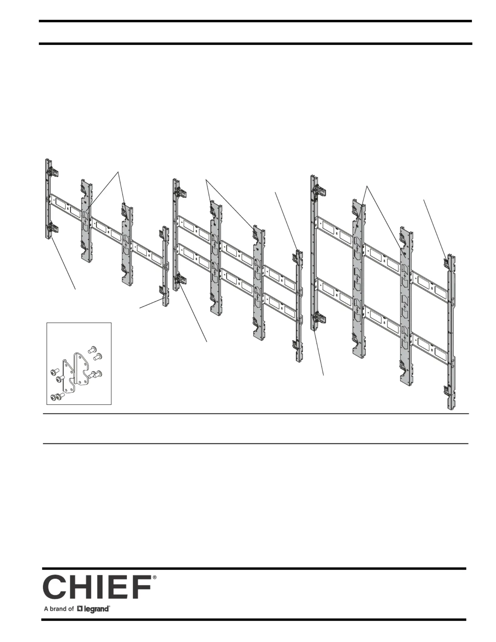
INSTALLATION INSTRUCTIONS
TILD1X4NE1-L
TILD1X3NE1-L
TILVAB2
Accessory
(Standard three-upright configuration shown for each model.
Configuration will vary based on application)
TILD1X3NE1-M
TILD1X3NE1-R
TILD1X4NE1-M
TILD1X4NE1-R
TILD1X5NE1-L
TILD1X5NE1-M
TILD1X5NE1-R
Nanolumens LED Wall Mounts / Accessory
Spanish Product Description
German Product Description
Portuguese Product Description
Italian Product Description
Dutch Product Description
French Product Description
TILD1xXNE1 Series
Tuotetiedot
| Merkki: | Chief |
| Kategoria: | Litteän paneelin tuki |
| Malli: | TILD1X5NE1-L |
Tarvitsetko apua?
Jos tarvitset apua merkille Chief TILD1X5NE1-L esitä kysymys alla ja muut käyttäjät vastaavat sinulle
Litteän paneelin tuki Chief Käyttöohjeet

3 Huhtikuuta 2025
3 Huhtikuuta 2025
3 Huhtikuuta 2025
3 Huhtikuuta 2025
9 Maaliskuuta 2025
6 Helmikuuta 2025
31 Tammikuuta 2025
30 Tammikuuta 2025
30 Tammikuuta 2025
22 Tammikuuta 2025
Litteän paneelin tuki Käyttöohjeet
Viimeisimmät Litteän paneelin tuki Käyttöohjeet
2 Huhtikuuta 2025
2 Huhtikuuta 2025
2 Huhtikuuta 2025
2 Huhtikuuta 2025
2 Huhtikuuta 2025
2 Huhtikuuta 2025
2 Huhtikuuta 2025
2 Huhtikuuta 2025
2 Huhtikuuta 2025
2 Huhtikuuta 2025