Speco Technologies SXU24V Käyttöohje
Speco Technologies Ei luokiteltu SXU24V
Lue alta 📖 käyttöohje suomeksi merkille Speco Technologies SXU24V (2 sivua) kategoriassa Ei luokiteltu. Tämä opas oli hyödyllinen 55 henkilölle ja sai 4.5 tähden keskimäärin 6 käyttäjältä
Sivu 1/2
®
Install Guides
SXU24V
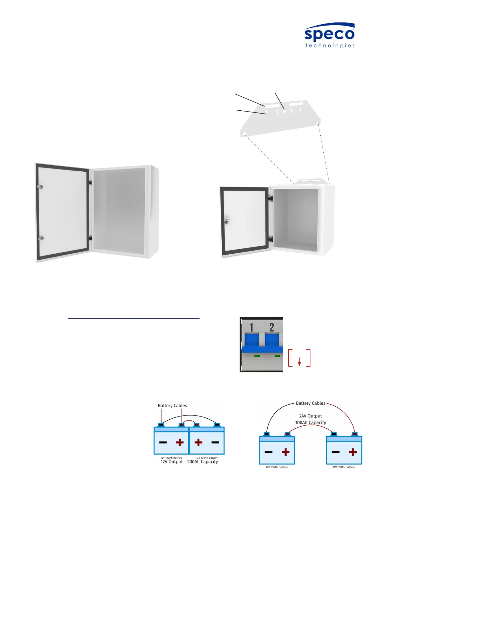
STEP 1
1. Check to ensure that all breakers are in the “OFF” position
before connecting any wires to the terminal blocks.
Mounting
the Enclosure
The SXU and SXA enclosures are designed
to be mounted to a wall or pole. The
enclosure utilizes an integrated mounting
plate on the back.
U-bolt
Hose Clamp
Lag Bolt
Install Guide
Mounting the enclosure
UPS Backup Kits
The AL2 and AL5 enclosures are designed to be mounted
to a wall or pole. The AL2 utilizes an integrated mounting
plate on the back of the enclosure.
The AL5 Enclosure comes integrated with Unistrut attached
to the back of the enclosure, and can be mounted usin
any applicable unistrut mountin hardware found at
most hardware stores.
AL2 Enclosure
AL5 Enclosure
Phone : + (208) 904-04244774 South Hwy 191, Rexburg, ID 83440E-Mail : support@vorpenergy.com
Unistrut
Rear of AL5 Enclosure
WIRING
Wiring the UPS backup Kit
Check to ensure that all breakers are in the “OFF” position
before connecting any wires to the terminal blocks.
Step 1
Step 2
Phone : + (208) 904-0424
4774 South Hwy 191, Rexburg, ID 83440
E-Mail : support@vorpenergy.com
Cable Gland
- If your part # ends with -12, connect your two 12 Volt Batteries in parallelto keep the battery voltage at 12VDC.
- If your part # ends with -24, connect your two 12 Volt Batteries in seriesto create a 24VDC Battery Bank.
Step 3
Ensure that the Voltage Selector Switch is set to the appropriate
Voltage. (Located to the Left of AC Input on Battery Charger)
- 115 VAC (90 to 132 VAC) *Slide Switch Towards Faceplate
- 230 VAC (180 to 264 VAC) *Slide Switch Away From Faceplate
Step 4
Passing through the provided cable gland, connect the AC power to
the AC Battery Charger using the provided butt connectors.
Step 5
Connect 12/24 VDC Equipment to the green phoenix terminal on the
faceplate. Connect any IP Equipment to the provided PoE Injectors
mounted on the DIN rail
Step 6
Power up the system by first powering the Battery Charger with the
ON/OFF switch located behind the AC Input. Then flip Breaker 1
followed by Breaker 2.
Parallel ConnectionSeries Connection
Voltage Selector Switch
ON/OFF Switch
AC Input
Phoenix Terminal
*In cold climates SLA batteries require insulation
STEP 2
1. If your part # ends with -12V,
connect your two 12 Volt
Batteries in parallel to keep
the battery voltage at 12VDC.
2. If your part # ends with -24V,
connect your two 12 Volt Bat-
teries in series to create
a 24VDC Battery Bank.
U-bolt
Hose Clamp
Lag Bolt
Install Guide
Mounting the enclosure
UPS Backup Kits
The AL2 and AL5 enclosures are designed to be mounted
to a wall or pole. The AL2 utilizes an integrated mounting
plate on the back of the enclosure.
The AL5 Enclosure comes integrated with Unistrut attached
to the back of the enclosure, and can be mounted usin
any applicable unistrut mountin hardware found at
most hardware stores.
AL2 Enclosure
AL5 Enclosure
Phone : + (208) 904-04244774 South Hwy 191, Rexburg, ID 83440E-Mail : support@vorpenergy.com
Unistrut
Rear of AL5 Enclosure
OFF
Tuotetiedot
| Merkki: | Speco Technologies |
| Kategoria: | Ei luokiteltu |
| Malli: | SXU24V |
Tarvitsetko apua?
Jos tarvitset apua merkille Speco Technologies SXU24V esitä kysymys alla ja muut käyttäjät vastaavat sinulle
Ei luokiteltu Speco Technologies Käyttöohjeet

18 Maaliskuuta 2025
12 Maaliskuuta 2025
25 Tammikuuta 2025
24 Tammikuuta 2025
23 Tammikuuta 2025
16 Tammikuuta 2025
16 Tammikuuta 2025
16 Tammikuuta 2025
16 Tammikuuta 2025
16 Tammikuuta 2025
Ei luokiteltu Käyttöohjeet
Viimeisimmät Ei luokiteltu Käyttöohjeet
9 Huhtikuuta 2025
9 Huhtikuuta 2025
9 Huhtikuuta 2025
9 Huhtikuuta 2025
9 Huhtikuuta 2025
9 Huhtikuuta 2025
9 Huhtikuuta 2025
9 Huhtikuuta 2025
9 Huhtikuuta 2025
9 Huhtikuuta 2025