Perlick 69526-2LG Käyttöohje
Perlick Digitalkameraer 69526-2LG
Lue alta 📖 käyttöohje suomeksi merkille Perlick 69526-2LG (28 sivua) kategoriassa Digitalkameraer. Tämä opas oli hyödyllinen 61 henkilölle ja sai 4.5 tähden keskimäärin 2 käyttäjältä
Sivu 1/28
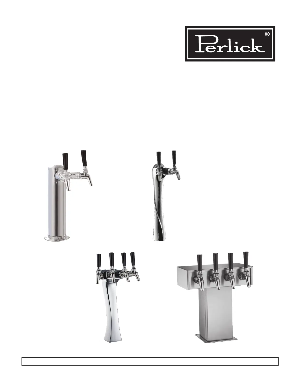
Installation
Instructions
Dispensing Towers
Draft Arm, Lucky, Panther or Tee Towers
PERLICK CORPORATION 8300 W. Good Hope Road, Milwaukee, WI 53223 • 800.558.5592 • perlick.com
Form No. Z2351
Rev. 11.2.22
Tee Tower
Lucky Tower
Panther Tower
Draft Arm
Tuotetiedot
| Merkki: | Perlick |
| Kategoria: | Digitalkameraer |
| Malli: | 69526-2LG |
Tarvitsetko apua?
Jos tarvitset apua merkille Perlick 69526-2LG esitä kysymys alla ja muut käyttäjät vastaavat sinulle
Digitalkameraer Perlick Käyttöohjeet

16 Lokakuuta 2024
16 Lokakuuta 2024
16 Lokakuuta 2024
16 Lokakuuta 2024
16 Lokakuuta 2024
16 Lokakuuta 2024
16 Lokakuuta 2024
16 Lokakuuta 2024
16 Lokakuuta 2024
16 Lokakuuta 2024
Digitalkameraer Käyttöohjeet
Viimeisimmät Digitalkameraer Käyttöohjeet
30 Maaliskuuta 2025
7 Helmikuuta 2025
31 Joulukuuta 2025
24 Joulukuuta 2024
20 Joulukuuta 2024
11 Joulukuuta 2024
16 Lokakuuta 2024
15 Lokakuuta 2024
15 Lokakuuta 2024
15 Lokakuuta 2024