Microchip SR10 Käyttöohje
Microchip Ei luokiteltu SR10
Lue alta 📖 käyttöohje suomeksi merkille Microchip SR10 (4 sivua) kategoriassa Ei luokiteltu. Tämä opas oli hyödyllinen 28 henkilölle ja sai 4.1 tähden keskimäärin 8 käyttäjältä
Sivu 1/4
Supertex inc.
Supertex inc.
www.supertex.com
SR10DB1
Doc.# DSDB-SR10DB1
A040113
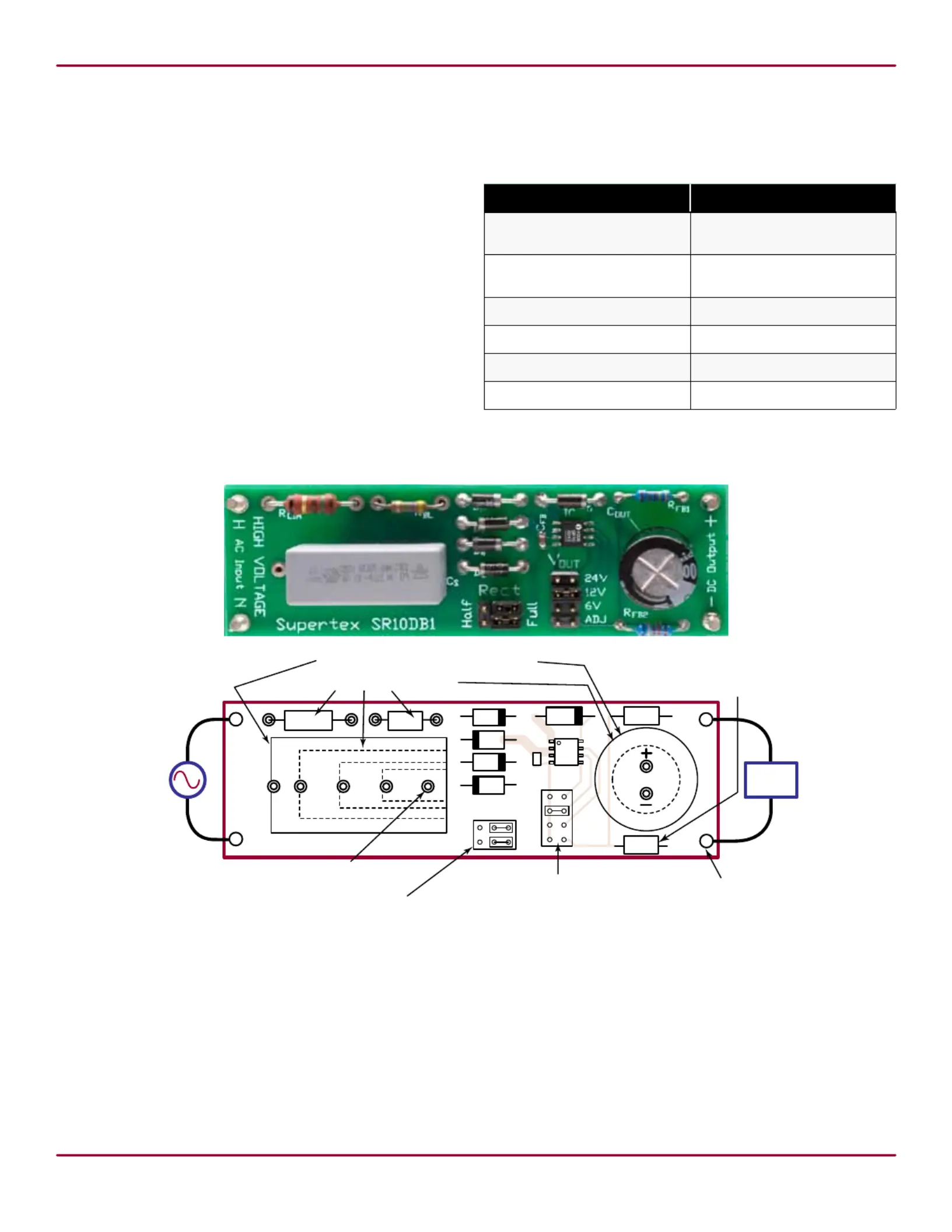
- DC Output +
24V
12V
6V
ADJ
HIGH EVOLTAG
Supertex SR10DB1
C
OUT
AC Input
90-275VRMS
50/60Hz
H
N
+
–
Load
R
FB1
and R
FB2
optional for output voltages other
than 6, 12, or 24V. Adjustment range is 6 - 28V.
Pre-configured for 9V. Pads for 0603 and 0805.
DC Output:
6, 12, 24V or
adjustable 6 - 28V.
Jumper-selectable full-wave
or half-wave rectification.
Both jumpers must be in the
same position, left or right.
Jumper-selectable output voltage.
Jumper must be present. When in
the ADJ position, R
FB1
and R
FB2
must be present.
Output minus is
connected to AC line
neutral when configured
for half-wave rectification.
R
FB1
R
FB2
D
2
D
1
D
4
D
3
R
BL
R
LIM
C
S
D
OUT
C
FB
One lead must always
be in this position
Socketed components.
Accomodates various capacitor sizes
IC
1
H Input N AC
Rect
Half
Full
V
OUT
Board Layout and Connection Diagram
Inductorless Switching
Power Supply Demoboard
Specications
ParameterValue
AC Input
90VAC to 275VAC
50Hz to 60Hz
Output voltage
6V, 12V, 24V ±10%
or 6-28V using divider
Output current
1
up to 50mA
No-load input power
1
as low as 20mW
Efciency
1
up to 75%
Actual board size88mm x 28mm
Introduction:
The Supertex SR10 is an inductorless switching power sup-
ply controller intended for operation directly from a rectied
120/240VAC line. Due to the capacitor-coupled, switched
shunt topology (CCSS), it exhibits low standby power and
good efciency while employing no magnetics nor high volt-
age electrolytic capacitors.
To meet a wide variety of applications, the SR10DB1 is
highly congurable. Many components are socketed. Half or
full-wave rectication is jumper-selectable. Output voltage is
jumper-selectable to 3 xed voltages or may be set anywhere
in the range of 6 - 28V using an on-board feedback divider.
AC Input (H and N)
Connect to the AC line. The ‘H’terminal should be connected
to the AC line hot conductor. The ‘N’ terminal should be con-
nected to the AC line neutral conductor. When congured for
half-wave rectication, the N terminal is connected to the DC
output minus (–) terminal.
DC Output (+ and –)
Connect the load to these terminals. Do not connect earth-
grounded loads or test equipment without using an isolation
transformer on the AC line.
Output voltage is jumper-selectable at 6, 12, or 24V, or it
may be set in the range of 6 - 28V using the R
FB
feedback
divider and setting the jumper to ADJ.
Notes:
1. Dependent upon conguration and degree of transient protection.
Tuotetiedot
| Merkki: | Microchip |
| Kategoria: | Ei luokiteltu |
| Malli: | SR10 |
Tarvitsetko apua?
Jos tarvitset apua merkille Microchip SR10 esitä kysymys alla ja muut käyttäjät vastaavat sinulle
Ei luokiteltu Microchip Käyttöohjeet

12 Maaliskuuta 2025
12 Maaliskuuta 2025
25 Helmikuuta 2025
25 Helmikuuta 2025
25 Helmikuuta 2025
25 Helmikuuta 2025
25 Helmikuuta 2025
25 Helmikuuta 2025
25 Helmikuuta 2025
25 Helmikuuta 2025
Ei luokiteltu Käyttöohjeet
Viimeisimmät Ei luokiteltu Käyttöohjeet
9 Huhtikuuta 2025
9 Huhtikuuta 2025
9 Huhtikuuta 2025
9 Huhtikuuta 2025
9 Huhtikuuta 2025
9 Huhtikuuta 2025
9 Huhtikuuta 2025
9 Huhtikuuta 2025
9 Huhtikuuta 2025
9 Huhtikuuta 2025