Festo DADP-SP-G9-6-R Käyttöohje
Festo Ei luokiteltu DADP-SP-G9-6-R
Lue alta 📖 käyttöohje suomeksi merkille Festo DADP-SP-G9-6-R (2 sivua) kategoriassa Ei luokiteltu. Tämä opas oli hyödyllinen 23 henkilölle ja sai 5.0 tähden keskimäärin 7 käyttäjältä
Sivu 1/2
DADP-SP-G9-...-R
Sub-base kit
Festo SE & Co. KG
Ruiter Straße 82
73734 Esslingen
Germany
+49 711 347-0
www.festo.com
Assembly instructions
8195137
2023-07a
[8195139]
8195137
Translation of the original instructions
© 2023 all rights reserved to Festo SE & Co. KG
1
Applicable documents
All available documents for the product
è
www.festo.com/sp.
DocumentProductContents
Operating instructionMini slide DGSS–
Operating instructionShock absorber DYEF, DYSS–
Tab. 1:
Applicable documents
2Safety
2.1
Safety instructions
–Only mount the product on components that are in a condition to be safely
operated.
2.2Intended use
The sub-base kit in combination with two shock absorbers on the mini slide DGSS
cushions its extended and retracted end position. The sub-base contains the axial
air connections for the mini slide.
3
Additional information
–Contact the regional Festo contact if you have technical problems
è
www.festo.com.
–Accessories
è
www.festo.com/catalogue.
4
Product Range Overview
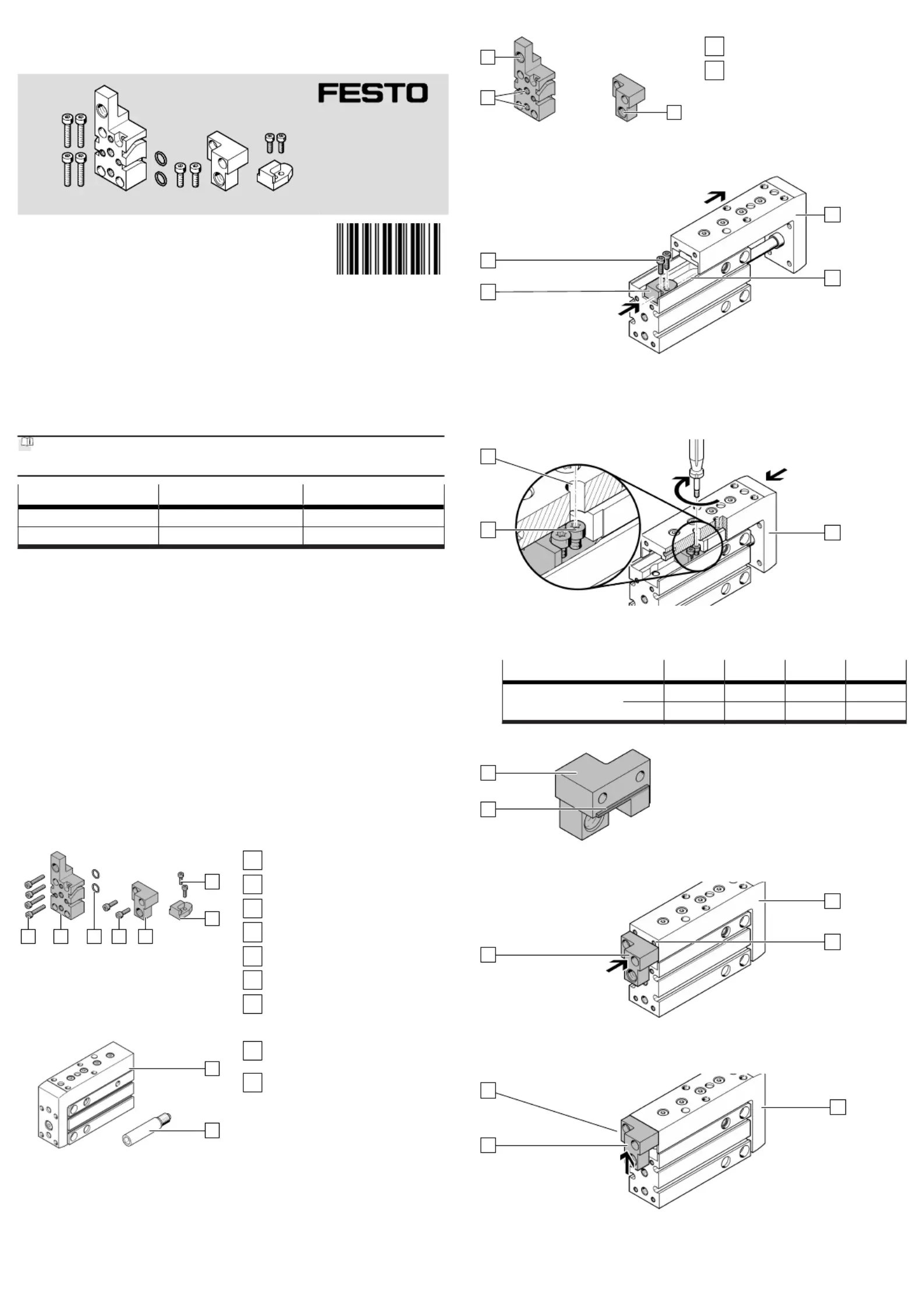
4.1Scope of delivery
1
2
35674
Fig.1
1
Screw (2x)
2
Stop (1x)
3
Stop element (1x)
4
Screw (2x)
5
O-ring (2x)
6
Connecting plate (1x)
7
Screw (4x)
4.2
Not in scope of delivery
8
9
Fig.2
8
Mini slide (1x)
DGSS
9
Shock absorber (2x)
DYEF-G8/DYSS-G8
5Product design
Z
Z
Y
Fig. 3:Product design
Y
Axial air connections
Z
Thread for shock absorber
6Assembly
1
A
B
2
Fig. 4:Pushing in stop
1.Extend the slide[A] manually.
2.Slide the stop into the slot[B].2
3.
Insert the screws into the holes of the stop.12
4.
Slide the stop to the end of the slot[B].2
A
C
1
Fig. 5:
Mounting stop
1.
Position the slide[A] so hole[C] is aligned with a screw.1
2.
Tighten the screw. Observe the tightening torque.1
DADP-SP-G9-6-10-16-20
ScrewM2 x 6M2.5 x 8M2.5 x 8M3 x 12
[Nm]0.3 ±15%0.5 ±15%0.7 ±15%0.9 ±15%
3.
Repeat this process for the second screw.1
C
3
Fig. 6:
Note the stop bar
•When installing the stop element, note the position of the stop bar[C].3
3
D
A
Fig. 7:
Aligning stop element
1.Retract the slide[A] manually.
2.
Position the upper edge of the stop element at the level of the thread[D].3
3
A
C
Fig. 8:
Attaching stop bar
1.Push the stop element upwards to the stop.3
Ä
The stop bar[C] is in contact with the slide[A].
2.Hold this position.
Tuotetiedot
| Merkki: | Festo |
| Kategoria: | Ei luokiteltu |
| Malli: | DADP-SP-G9-6-R |
Tarvitsetko apua?
Jos tarvitset apua merkille Festo DADP-SP-G9-6-R esitä kysymys alla ja muut käyttäjät vastaavat sinulle
Ei luokiteltu Festo Käyttöohjeet

30 Maaliskuuta 2025
30 Maaliskuuta 2025
30 Maaliskuuta 2025
30 Maaliskuuta 2025
30 Maaliskuuta 2025
30 Maaliskuuta 2025
30 Maaliskuuta 2025
30 Maaliskuuta 2025
30 Maaliskuuta 2025
30 Maaliskuuta 2025
Ei luokiteltu Käyttöohjeet
Viimeisimmät Ei luokiteltu Käyttöohjeet
9 Huhtikuuta 2025
9 Huhtikuuta 2025
9 Huhtikuuta 2025
9 Huhtikuuta 2025
9 Huhtikuuta 2025
9 Huhtikuuta 2025
9 Huhtikuuta 2025
9 Huhtikuuta 2025
9 Huhtikuuta 2025
9 Huhtikuuta 2025