Daikin DTA114A61 Käyttöohje
Daikin Ei luokiteltu DTA114A61
Lue alta 📖 käyttöohje suomeksi merkille Daikin DTA114A61 (4 sivua) kategoriassa Ei luokiteltu. Tämä opas oli hyödyllinen 40 henkilölle ja sai 4.8 tähden keskimäärin 7 käyttäjältä
Sivu 1/4
INSTALLATION
3
FXFQ
FXMQ
Minimum contact load: 1mA normally closed contact at 15VDC
Rated current: 3 A min.
Wire specifications: Vinyl cord with sheath or cable (2 wire)
Wiring thickness: 0.75 to 1.25 mm
2
Wiring length: 100 m max.
Minimum contact load: 1mA normally closed contact at 15VDC
Rated current: 3 A min.
Wire specifications: Vinyl cord with sheath or cable (2 wire)
Wiring thickness: 0.75 to 1.25 mm
2
Wiring length: 100 m max.
BSVQ
FX~
open
No error indicationNo error indication
Adaptor for Multi tenant Installation Manual
DTA114A61 • 61-9
(1) Connect this adaptor and the PCB of the indoor unit with the
provided relay harness (varying with each indoor unit model).
(2) Connect the 24VAC (±20%) power supply to the X1M terminals of
the adaptor through the normally closed contacts of the relay. Be
sure to contact the relay contacts to both poles of the power
supply so that the positive and negative lines of the power supply
will be turned off simultaneously. A transformer may be used for
the 24VAC power supply provided for each adaptor on the
condition that the transformer has a capacity of 24VA or over.
(3) Provide a relay (with a normally closed contact) between the T1
and T2 terminals of the PCB.
(4) Short-circuit the T1 and T2 terminals of the adaptor.
• An adaptor mounting plate and mounting box
are required in addition to the provided
component parts in the case of mounting the
adaptor to the following models.
FXFQ~P: KRP1H98
FXMQ~P: KRP4A96
FXAQ~M: KRP4A93
• Both ends of harness are for connection of
PCB of indoor unit (or BS unit) and for
connection of adaptor for multi tenant. Be
careful when connecting them.
1P223254-1C
Daikin Air Conditioner
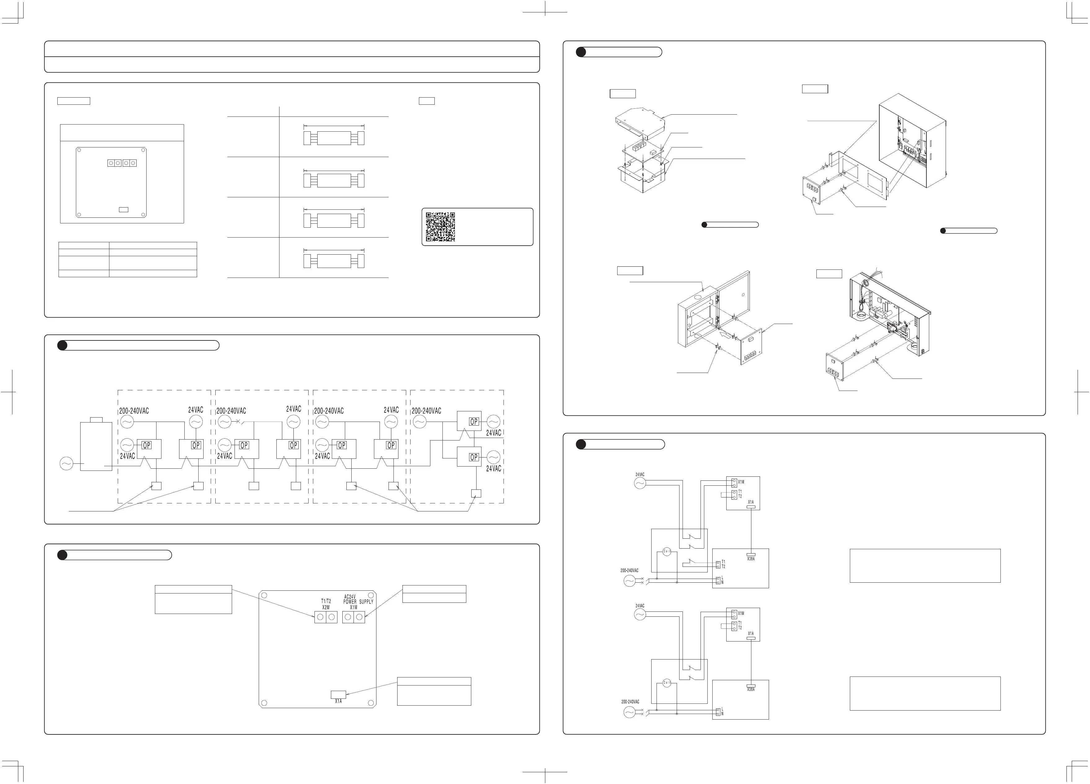
GENERAL DESCRIPTION OF SYSTEM
1
NAMES AND FUNCTIONS
2
AccessoriesNoteCheck that the following accessories are provided with the adaptor before installation.
Adaptor for Multi tenant
PCB support
Tiewrap
Relay harness
Installation Manual
4 pcs.
4 pcs.
4 pcs. (see the table on the right-hand
side for applicable models)
1 pc.
1 pc.
Applicable modelsRelay harness
FXFQ~P
FXMQ~P
BSVQ~P
FXAQ~M
700
UL electric wire
WhiteWhite, 4 pins
350
UL electric wire
WhiteWhite, 4 pins
260
UL electric wire
WhiteBlue, 3 pins
1900
VCTF electric wire
WhiteWhite, 3 pins
• The use of this adaptor allows the system to operate with no system error indication in the event of the interruption of power supply to other indoor units.
(In the case of the following diagram, there will be no error indication on the remote controllers of tenant 1 or tenant 3 or tenant 4 in the event of the
interruption of power supply to tenant 2.)
Contact input (T1/T2)
Receives power under ON/OFF
control for the indoor unit
through the contact relay.
Adaptor power supply
Receives 24VAC power
Indoor power supply
Supplies power to the indoor
unit through the provided
harness connected.
Lid of installation box
(KRP1H98, sold separately)
Mounting plate for adaptor PCB
(KRP4A96, sold separately)
Adaptor
PCB support
Installation box for adaptor PCB
(KRP1H98, sold separately)
Installation box for adaptor PCB
(KRP4A93, sold separately)
NOTE
1) Installation box for adaptor PCB is
required in addition to the provided
component parts in the case of
mounting the adaptor.
2) Connect the wiring to the adaptor PCB
first. The work will be easier.
(Refer to .)
NOTE
1) Mounting plate for adaptor PCB is
required in addition to the provided
component parts in the case of
mounting the adaptor.
2) Connect the wiring to the indoor PCB
first. The work will be easier.
(Refer to .)
Adaptor
PCB support
FXAQ
PCB support
Adaptor
BSVQ
Adaptor
PCB support
•
Example with FXFQ, FXAQ, and FXMQ
•
Example with BSVQ
(1)
(2)
(4)
This adaptor
(1)
(2)
(3)
This adaptor
Three-pole contact
(Field supply)
Two-pole contact
(Field supply)
PCB of indoor unit
BSVQ PCB
(1) Connect the adaptor and BSVQ PCB through the relay harness.
(2) Connect the 24VAC (±20%) power supply to the X1M terminals of
the adaptor through the normally closed contacts of the relay. Be
sure to contact the relay contacts to both poles of the power
supply so that the positive and negative lines of the power supply
will be turned off simultaneously. A transformer may be used for
the 24VAC power supply provided for each adaptor on the
condition that the transformer has a capacity of 24VA or over.
(3) Short-circuit the T1 and T2 terminals of the adaptor.
〈〈Ceiling-mounted Duct Type〉〉〈〈Ceiling-mounted Cassette Round-flow Type〉〉
〈〈BS unit〉〉
NOTE)
Installation box for adaptor PCB is
required in addition to the provided
component parts in the case of
mounting the adaptor.
(3)
METHOD OF WIRING
5
METHOD OF WIRING
5
Tenant 1Tenant
2
Tenant
3
Tenant
4
ELECTRIC WIRING
4
For the installation instructions
of models NOT mentioned
in this manual, scan the QR code
to access the website with photo
manuals.
〈〈Wall-mounted type〉〉
Tuotetiedot
| Merkki: | Daikin |
| Kategoria: | Ei luokiteltu |
| Malli: | DTA114A61 |
Tarvitsetko apua?
Jos tarvitset apua merkille Daikin DTA114A61 esitä kysymys alla ja muut käyttäjät vastaavat sinulle
Ei luokiteltu Daikin Käyttöohjeet

9 Huhtikuuta 2025
9 Huhtikuuta 2025
9 Huhtikuuta 2025
9 Huhtikuuta 2025
9 Huhtikuuta 2025
9 Huhtikuuta 2025
9 Huhtikuuta 2025
11 Helmikuuta 2025
11 Helmikuuta 2025
10 Helmikuuta 2025
Ei luokiteltu Käyttöohjeet
Viimeisimmät Ei luokiteltu Käyttöohjeet
9 Huhtikuuta 2025
9 Huhtikuuta 2025
9 Huhtikuuta 2025
9 Huhtikuuta 2025
9 Huhtikuuta 2025
9 Huhtikuuta 2025
9 Huhtikuuta 2025
9 Huhtikuuta 2025
9 Huhtikuuta 2025
9 Huhtikuuta 2025